RMPS and RLIM on a ControlLogix: Ramping a Setpoint Instead of Stepping It
A sequence step writes 75.0 into the speed reference of a PowerFlex on a packing line that was sitting at 20.0, and the drive comes back with an overcurrent on acceleration about 400 ms later. Nothing in the controller did anything wrong. A REAL tag went from one legal value to another legal value in a single scan, and the drive was asked to find 55% more speed in whatever its accel ramp allows, against a belt that was already loaded.
The Logix answer to that is one of two Process instructions, and which one depends on whether you need a rate or a recipe.
RLIM is the rate limiter: one input, one output, a rising rate and a falling rate that do not have to be the same number, and the output chases the input no faster than those rates allow. RMPS is the ramp-soak profile: an array of segments, each with a target value, a ramp to reach it and a time to hold it, the thing you want when a heat treatment has to follow a written cycle. Both are Function Block and Structured Text only. Neither is available in ladder, and that single line in the manual is what sends most people off to write their own.
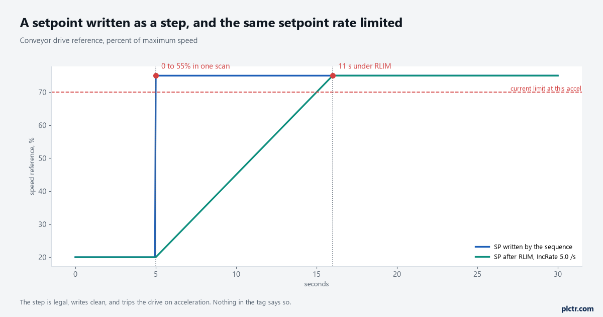
Eleven seconds against one scan. The step is not an error and no instruction refuses it; the drive is the only thing in the loop with an opinion.
What a step actually costs downstream
The drive is the loud case. The quiet ones are worse.
A control valve given a 40% step will slam, and on a liquid line that is a water hammer the pipework did not ask for; a positioner with a 4 second stroke time will spend those 4 seconds at full air while the loop above it winds up integral against an error that is not its fault. A heater given a step in setpoint overshoots, because a PID tuned for load changes is being asked to answer a setpoint change, and derivative sees an infinite rate of change on the error at the instant the number moves. A gearbox given a step in commanded speed puts the whole step into backlash and then into the coupling. None of these show up as a fault code. They show up as a valve that needs reseating every nine months, an oven that runs 8 degrees hot for the first twenty minutes of every batch, and a coupling somebody keeps replacing.
So the ramp is not decoration. It is the specification of how fast the process is allowed to be asked to change.
If the loop downstream is a PIDE, there is a second reason to put the ramp in front of it rather than inside it: a PIDE whose setpoint moves slowly is doing setpoint tracking, which its gains were probably tuned for, and the bump test that set those gains is worth re-reading before you decide the loop is at fault — PIDE gains, units and the first bump test covers that side. The drive has its own opinion about this, set in its own parameters.
The interaction between a PLC-side ramp and a drive-side decel time is exactly what produces F005 overvoltage on stop on a PowerFlex 525.
RLIM: two rates and a bypass
The RATE_LIMITER structure is small enough to read in one sitting.
In is the signal you want followed. IncRate and DecRate are the maximum increment and decrement rates in per-second units, both of them validated as non-negative — feed either a negative number and the instruction substitutes 0.0 and sets its own status bit rather than faulting the controller. ByPass is a BOOL that, when true, sets Out = In and abandons the limiting entirely, which is what you want wired to a jog mode or a manual station.
Out is the result. DeltaT is an output, and it reports how much time the instruction believed had passed.
Two rates rather than one is the part worth designing around.
On a conveyor the rising rate is a process constraint and the falling rate is a safety one: you may only be able to accelerate at 5% per second without disturbing product, while you want to be able to decelerate at 12% per second when something jams downstream. Set IncRate to 5.0 and DecRate to 12.0 and the same instruction gives you both. And if the input reverses mid-ramp — the sequence asks for 75, then changes its mind at 48 and asks for 30 — the instruction simply switches to the other rate from wherever the output has got to. There is no memory of the old target and no overshoot. That is a genuine advantage over a hand-written ramp, where the usual bug is exactly this case: a counter that was counting up towards a target and now has to be told to count down.
One behaviour to know before you commission it. On the instruction’s first scan, Out is initialised with the value of In — the rate limiter does not ramp up from zero after a download, it starts wherever the input already is. That is almost always what you want, and it means you cannot use an RLIM to give a machine a soft start on power-up.
The part people get wrong: the instruction does not own a clock
Here is the thing that makes an RLIM behave differently in two projects that look identical.
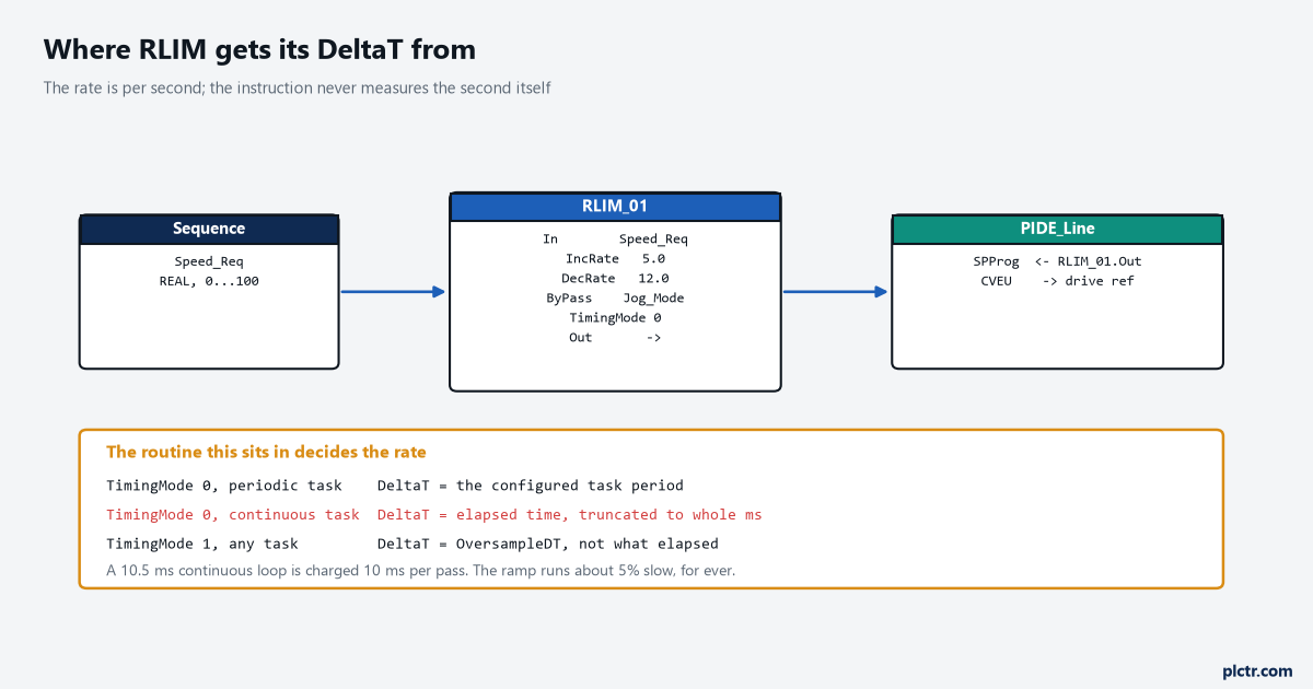
The three rows at the bottom are the whole problem. The rate is per second and the instruction is told how long a second is by something outside it.
RLIM is on the list in 1756-RM006P of instructions that support timing modes, along with PIDE, INTG, LPF, SCRV and about ten others. TimingMode 0 is Periodic and is the default. In Periodic mode, if the instruction executes in a periodic task, DeltaT is the period of the task — not the measured time, the configured number. If it executes in an event or continuous task, DeltaT is the elapsed time since the previous execution, and the manual adds a detail people read past: the controller truncates that elapsed time to whole milliseconds, so an elapsed 10.5 ms is charged as 10 ms. A continuous task that happens to loop in 10.5 ms therefore under-counts time by about five percent, permanently, and your 5.0 per second ramp is really a 4.76 per second ramp. Nothing reports this. The recommendation in the manual is a single sentence — put instructions that use this mode in a routine that executes in a periodic task — and that sentence is the entire reason this article has a section about tasks in it.
Then there is the failure that is genuinely silent.
The manual lists five ways a discontinuity gets into the output, and two of them are about the task rather than the instruction: the instruction not being executed during a scan, and the task scan rate changing while the task is running. Both of those happen for the same mundane reason. A periodic task that overlaps — triggered again while it is still running from the last trigger — has the new trigger disregarded; 1756-PM005M is blunt about it and warns that you might miss an important execution of the task. The controller logs a minor fault and increments the Task Overlap Count on the task’s Monitor tab, and neither of those is anything anybody looks at on a machine that is running. But the RLIM in that task still thinks DeltaT is the configured period, because in Periodic mode that is where it gets the number from. Ten percent of the triggers dropped means a ramp that takes eleven percent longer, silently, and nothing in the control system says so.
Three things to check when a ramp is running slow and nobody changed the rate.
Look at the Task Overlap Count first, because it takes ten seconds and it is the answer more often than the rate is. Look at whether the routine got moved: somebody consolidating tasks and dragging a process routine from a 100 ms periodic task into MainTask is a change that no code review flags, because not a line of code changed. And look at the task period itself: it is the one number that changes the rate without touching the instruction.
Sizing that period is the same arithmetic as everything else in PLC scan time and cycle time.
RMPS: segments, soaks, and what “soak complete” means
RMPS is the bigger instruction and it earns the extra parameters when you have a recipe.
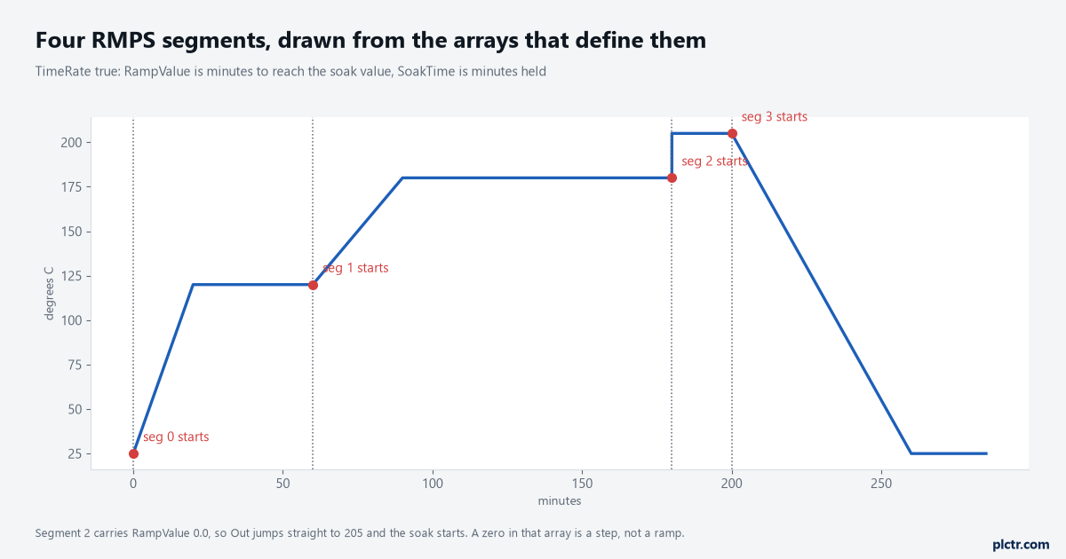
Four segments from three arrays. The vertical face at 180 minutes is a RampValue of 0.0, which is legal and is not a ramp.
Three REAL arrays define the profile, all of them at least as long as NumberOfSegs: RampValue, SoakValue and SoakTime, indexed 0 to NumberOfSegs-1. SoakValue[n] is the target the output is heading for during segment n, and SoakTime[n] is the hold once it gets there, in minutes. RampValue[n] is the travel, and how it is read depends on one BOOL: with TimeRate true it is the time in minutes to reach the soak value, and with TimeRate false it is a rate in units per minute.
All segments use the same convention, so that flag is a project decision rather than a per-recipe one.
The ramp is complete when Out reaches SoakValue for the segment. The soak is complete when Out has been held there for SoakTime, at which point CurrentSeg increments and the next one starts.
SoakTimeLeft counts that hold down in minutes and is the output your HMI should be showing, because it is the only number on the block that answers “how long until this step finishes”. Two further BOOLs decide whether the profile is chasing a clock or chasing the process. With GuarRamp set, the instruction watches the difference between Out and PV, and if the process has fallen further behind than RampDeadband, it stops advancing the output until the process catches up — GuarRampOn goes true while that is happening. GuarSoak does the equivalent for the hold: if PV drifts outside SoakDeadband, the soak timer is cleared, so a soak that loses temperature does not quietly count itself down anyway.
Where the soak time is a product specification rather than a convenience, those two flags decide whether you have a profile or a process.
And CyclicSingle decides what happens at the end: false runs the profile once and stops, true sets CurrentSeg back to 0 and runs it again.
One commissioning surprise, from the execution table rather than the description. On its first run, RMPS clears CurrentSeg to 0 and puts itself into Operator Manual mode. It does not start the profile. Something — your logic through ProgAutoReq, or an operator through a faceplate — has to ask it to go to Auto, and until that happens Out is whatever OutOper says it is. A first commissioning where the oven never heats and the block shows no fault is almost always this.
Where RMPS and RLIM part company on time
This one surprised me, and it is the reason both instructions are in one article rather than two.
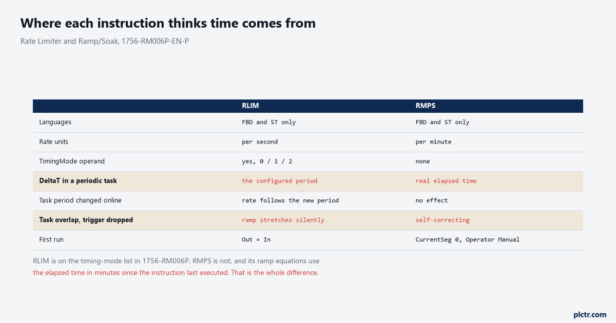
Two tinted rows. RMPS has no TimingMode operand because it does not need one.
RMPS is not on the timing-mode list. It has no TimingMode, no OversampleDT, no RTSTime — and its ramp equations, both the time-based one and the rate-based one, are written against the elapsed time in minutes since the instruction last executed. Real elapsed time, measured, not a configured period. So the two instructions in this article answer the same question in opposite ways: RLIM in its default mode trusts the task configuration and is wrong when the task misbehaves, while RMPS measures and is right regardless of where you put it. Put an RMPS in a continuous task and the profile still takes the right number of minutes. Put an RLIM there and it does not.
That is not an argument for putting RMPS anywhere you like. A profile updated every 300 ms is fine for an oven and is not fine for anything with a short time constant, and the coarser the update the coarser the staircase your PID sees. But it does mean the two instructions need different amounts of care about where they live, and treating them as one family is how the RLIM ends up in MainTask.
One more instruction is worth naming before you go and build your own.
For a ramp that is smooth in its own derivative, with the acceleration eased in and out rather than switched on, the instruction is SCRV. It adds a JerkRate in units per second cubed to the AccelRate and DecelRate in units per second squared. Worth knowing it exists, and worth knowing its controller list is not identical: the SCRV page names the CompactLogix 5370 and 5380, the ControlLogix 5570, 5580 and 5590, and the GuardLogix 5370, but does not list the Compact GuardLogix 5380 or the GuardLogix 5580 that RLIM and RMPS both do. Check the page for the firmware in front of you rather than assuming the Process set is uniform.
When to write the ramp yourself
There is an honest case for three lines of Structured Text, and it is narrower than people think.
The case is a ladder project with no Function Block routines in it, one setpoint that needs a rate limit, and no appetite for adding a periodic task and an FBD routine to a program that a maintenance electrician has to be able to read at 3am.
An ST routine in that same periodic task, holding SP_Out := SP_Out + LIMIT_RATE * PERIOD; with a clamp at the target, runs to twelve lines including the comments, and everybody on site can follow it. If you have not written ST before, the constructs you need are all in Structured Text for people who write ladder.
What you are buying with those twelve lines is readability. What you are giving up is real.
You now own the DeltaT problem yourself, and you own it worse, because your constant is hard-coded and the RLIM at least reads the task period at runtime. Change the task from 100 ms to 250 ms and the instruction adjusts while your ST routine ramps two and a half times too fast, in the direction of the thing you put the ramp in to prevent. You also lose ByPass, the separate decrement rate, and the reversal handling that RLIM gets right without being asked.
So: write it yourself only if the alternative is not doing it at all. Then put the period in a named constant beside the rate, where the two cannot be changed apart.
What to check next
Put RLIM_01.DeltaT on a trend for five minutes. It is an output parameter on the block, it is in seconds, and it will tell you in one screen whether the instruction is getting the time it thinks it is getting — a flat line at the task period is healthy and anything else is the answer to why the ramp is slow. Then open the task’s Monitor tab and read the Overlap Count before you touch a rate. If the profile rather than the rate is the problem, put CurrentSeg and SoakTimeLeft on the same trend as Out and the segment that is not behaving names itself. And if the thing at the end of the ramp is an analogue output rather than a drive, the clamping and fail-position decisions that go with it are in an analogue output that drives a valve — a rate limiter in front of a module that jumps to its fault value on a connection loss has not bought you anything. The timer-based version of this same “what happens between scans” question, for the ladder instructions people reach for first, is in TON, TOF and RTO on a false rung.