A 1756-OF8 is a 0…20 mA module, and at full counts it puts out 21.29 mA. Nothing in the hardware knows that the positioner on the end of the wire wants 4 mA for closed and 20 mA for open, or that 0 mA on an air-to-open valve is the same as closed and 21 mA is a positioner driven past its stop. Analogue output scaling is only the first of the three places those facts have to be told to the module: the scaling, the clamps, and the two values the module writes by itself when the controller stops talking to it.
The short version, in three moves.
Scale the channel so 4 mA is 0 and 20 mA is 100, in floating point, because scaling is not available in integer mode. Clamp it at 0 and 100 in the same engineering units. Then decide what the valve should do when the controller goes to Program and when the connection drops, and set the fault value and the program value so the module agrees with the spring. The Siemens side, with an SM 1232, has the same three decisions with different names and one extra rule about what happens when the logic writes a number the module cannot make.
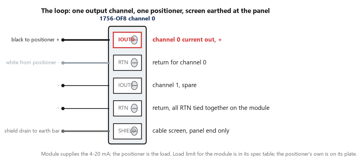
One channel, one positioner, one screen. The module is the current source and the positioner is the load; the returns are common on the module, which matters when the second valve arrives and somebody expects channel isolation.
Analogue output scaling: which number means which current
The manual describes scaling as choosing two points along the module’s operating range and applying low and high values to those points. On an input that is 4 mA equals 0% and 20 mA equals 100%. On the output it is the same sentence in the other direction: Low Signal 4 mA against Low Engineering 0, High Signal 20 mA against High Engineering 100, and a tag written with 35.0 leaves the terminal at 9.6 mA. The manual prints the straight line it uses, and it is the one you expect: Data equals Low Engineering plus (Signal minus Low Signal) times (High Engineering minus Low Engineering) over (High Signal minus Low Signal). Choosing two points does not shrink the module. The manual is explicit that the module’s range and its resolution remain constant regardless of how you scale it, so the channel can still produce 0 mA and can still produce 21 mA if something asks for -25 or 108. That is what the clamps are for.
Scaling on its own is not enough, and it never was.
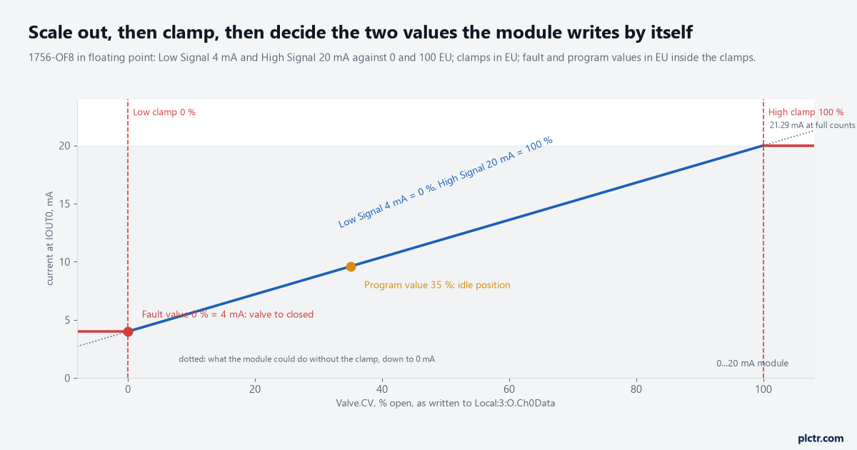
The blue line is the scaling. The red ends are the clamps, and the dotted continuations are what the module would do without them. The two dots are the values it writes on its own.
One habit from the input side carries over, and one does not. The engineering units can be anything you like — percent open, litres per minute, degrees of stem travel — as long as the loop’s CV is in the same units, and percent is the least surprising choice because a positioner’s own display is in percent. What does not carry over is the input article’s underrange arithmetic: an output written below the low signal is not an alarm condition on the module, it is a request the module will honour unless clamped, and a positioner sent 2.7 mA will do whatever its manufacturer decided 2.7 mA means. The PLC-side arithmetic for the input direction is in reading a 4-20 mA transmitter into a 1756-IF8, and the same numbers apply here reversed.
Percent in, milliamps out, and the module keeps its whole range underneath.
Clamp: in engineering units, and re-entered when the scaling changes
Clamping, per the manual, limits the output from the analog module to remain within a range configured by the controller, even when the controller commands an output outside that range. The channel has a high clamp and a low clamp — Ch0ConfigHighLimit and Ch0ConfigLowLimit in the floating-point configuration tags — and a value beyond either sets the matching limit alarm bit, Ch0HLimit or Ch0LLimit, and transitions the output to that limit but not beyond it. The manual’s own example is a voltage one: high clamp 8 V, low clamp -8 V, controller sends 9 V, the module applies 8 V and tells the controller it did. Set them at 0 and 100 for a valve, and not at 4 and 20, because the clamps are in engineering scaling units, not in milliamps, and this is the trap the manual flags in bold: clamp values are in engineering scaling units and are not automatically updated when the engineering high and low scaling units are changed, and failing to update them generates a small output signal that could be misinterpreted as a hardware problem. The Compact 5000 manual repeats it with an example that is easy to picture. Scaling 0 to 100%, clamps 0 to 100%, then somebody changes the high engineering value to 90% and the high clamp is still 100. The module now clamps at a number it can no longer reach, and the channel looks broken from the faceplate. Clamping is a floating-point feature. So is scaling, so is Run-mode ramping, so is Hold Last State or a user value in fault and program mode. The table in the manual that lists what integer mode gives up is worth a look before anyone picks Integer for speed: ramp to program value, ramp to fault value and hold for initialization are what remain. A valve output configured in integer mode has no clamps, and its fault value is entered in counts.
Floating point, then. The speed argument for integer mode is not worth a valve.
Clamps limit what the controller can ask for. They do not limit what the module does on its own, which is the next section, and the manual notes that the fault and program values must fall within the range of the high and low clamp values — so set the clamps first.
Fail position: two values the module writes without you
Two things take the controller away from the valve. The controller goes to Program mode, for a download or because somebody turned the key. Or the connection to the module drops, a pulled cable or a faulted adapter, and the manual is direct about that one: outputs always go to Fault Mode if communications fail in Run Mode.
Two events, two values, and both are yours to set.
For each of the first two the channel has a mode bit and a value. Ch0ConfigProgMode selects, on transition to Program mode, either hold last state or go to a user-defined value, and Ch0ConfigProgValue is that value in engineering units. Ch0ConfigFaultMode and Ch0ConfigFaultValue do the same for a communication fault. Both values sit inside the clamps. And there is a ramp for each: Ch0ConfigRampToProg and Ch0ConfigRampToFault make the move happen at Ch0ConfigMaxRampRate, which the manual expresses in percent of full scale per second, rather than as a step. Now the valve. An air-to-open, spring-to-close valve closes on loss of instrument air whatever the PLC does, and it closes on 4 mA because that is what the positioner does with 4 mA. So the fault value that agrees with the spring is 0%. The program value is a separate decision: on a machine that is downloaded to during production, hold last state keeps the process where it was while the download runs, and a program value of 0% shuts the line every time somebody goes online with a change. Neither is wrong.
What is wrong is not deciding, because the module’s default, mode bit clear, is hold last state, and that means a valve that stays at 62% open for as long as the cable is unplugged, and the operator will not know from the HMI, because the HMI is showing the controller’s tag, not the module’s echo.
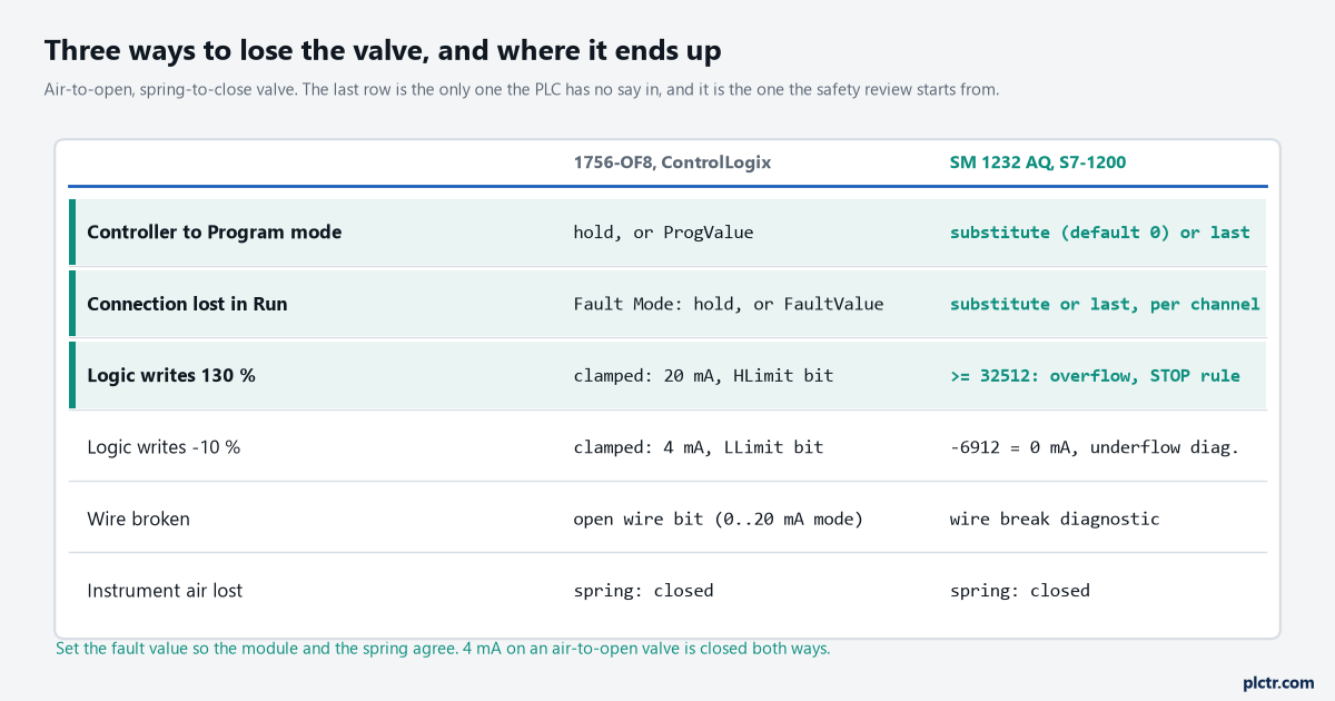
The last row is the one the PLC has no say in, and the fault value is chosen to agree with it. On an air-to-close valve every entry in the table flips, and the fault value becomes 100%.
The Compact 5000 modules add one parameter the 1756 modules do not have, and it is the useful kind. On a 5069-OF8 the fault state has a duration: if the output is configured to transition to a specific value after the connection fault, you must define how long it remains at that value — forever, or 1, 2, 5 or 10 seconds — before it transitions to a final fault state value. That is a two-stage fail.
Hold at the last good position for ten seconds in case the connection comes straight back, then go to closed.
A pressure-control valve that slams shut on a 200 ms network blip is a process upset; one that holds for two seconds and then closes is a fault handled properly.
The dead end: reading the echo and blaming the module
The output module sends back a data echo, which the manual describes as multicasting the channel data values that match the analog value that was sent to the module’s screw terminals. Local:3:I.Ch0Data is what the module thinks it is producing. When the valve sits at the wrong position, the first thing everybody does is compare the output tag with the echo, find them equal, and conclude the module is fine and the positioner is at fault.
Half the time the module is doing exactly what it was told and the telling was wrong.
The echo agrees with the tag because the tag is the problem. A CV from a loop whose output span was left at 0 to 1 lands on a channel scaled 0 to 100 as 0.62%, which is 4.1 mA, which is closed. The echo says 0.62 and the tag says 0.62 and they agree. The positioner was never the problem, and the PID article on this site covers what those spans do to a loop, PIDE gains, units and the first bump test. The other half of the time the clamp is the story: the echo reads 100.0 while the tag reads 130.0, Ch0HLimit is set, and the loop has wound up against a stop the module is quietly enforcing.
Hold for initialization, and the bump on every restart
There is one more checkbox that decides how a valve behaves at the worst moment, which is the first scan after a restart.
Hold for Initialization causes outputs to hold their present state until the value commanded by the controller matches the value at the output screw terminal within 0.1% of full scale, and it does so on three occasions the manual lists: initial connection after power-up, a new connection after a communications fault, and a transition to Run from Program. The Ch0InHold bit tells the logic the channel is waiting. Without it, a controller coming back from Program mode with Valve.CV at whatever it was writes that value to a valve that has been sitting at the program value, and the valve steps. With it, the module holds where it is until the logic has caught up, and the loop’s first job after a restart is to read the echo into its CV — a PIDE in manual with the CV preset to Local:3:I.Ch0Data — before it is switched to auto. The manual calls that a bumpless transfer.
On a big valve it is the difference between a restart and a water hammer.
The Siemens side: substitute value, and the overflow rule
An SM 1232 AQ is a ±10 V, 0 to 20 mA or 4 to 20 mA module, 13-bit in current mode, and its data word runs 0 to 27648 for the rated range. In the 4 to 20 mA range 0 counts is 4 mA and 27648 is 20 mA; there is no scaling dialog on the module, so the percent-to-counts arithmetic is in the program, and on a 1200 or 1500 that is NORM_X followed by SCALE_X into an Int, the same pair used the other way round in scaling an analogue input in FBD. The fail position lives in the device configuration rather than in a tag, and it has a name people skip past. For any output of a CPU, signal board or signal module, the manual says, you set the reaction on a RUN-to-STOP transition to either a substitute value, which you enter per channel and which defaults to 0, or to freezing the output at its last state. On the 4 to 20 mA range a substitute value of 0 is 4 mA, which is closed on the air-to-open valve, and that is a happier default than it first looks. And after power-up, the manual adds, the outputs are set to the substitute value whichever option was chosen.
The clamp is where the S7 differs and where it bites hardest. The output representation table runs above the rated range to an overshoot region: 27649 to 32511 counts is 20.0 to 22.81 mA, and the module produces it. Write 30000 and the valve is driven to 21.4 mA, which is past open. From 32512 upward the table says overflow, and the note under it says something a ladder programmer would not guess: in an overflow condition the analog output behaves according to the Reaction to CPU STOP setting, substitute value or keep last value. So an unclamped CV that overflows does not saturate at 20 mA. It sends the valve to the substitute value — closed — while the CPU stays in RUN and the logic shows 130%. Below zero the undershoot region runs to -6912 counts, which is 0 mA on the 4 to 20 range, and the module has a wire-break diagnostic in current mode and an underflow diagnostic to go with it.
Overflow closes the valve. Nobody expects that from a number that is too big. LIMIT on the percent value before SCALE_X, 0.0 to 100.0, is the clamp.
One instruction, and the overflow rule never gets a chance to run.
What to check next
Open the channel’s configuration and read four numbers back to yourself: the low and high signal, the low and high engineering value, the two clamps, and the fault and program values. Then disconnect the module’s cable with the valve at 50% and watch what the valve does, not what the HMI does. If it holds at 50%, the fault mode is still on its default and the decision was never made. If it goes to 4 mA, the module and the spring agree. Do the same with the key in Program. Then write the three answers on the loop sheet next to the tag name, because the next person to open the configuration will assume the defaults were chosen. The wider set of things an output card does that the logic never sees is in PLC I/O modules: sinking, sourcing, keying, scaling.