The 1756-IB16S Safety Input Card: Dual Channel, Test Pulses and What OSSD Means
Channels 0 and 8 look like the obvious pair for a dual-channel gate switch on a 1756-IB16S. They are directly opposite each other on the terminal block and the wiring is tidy. They are also the one pair the module will not let you pulse test, along with 1 and 9, 2 and 10, and every other input eight apart, because both of those inputs are served by the same test output and a pulse test has to come from two different sources to prove anything.
Use 0 and 1 instead, with TO-0 and TO-1. The tidy loom is the wrong loom.
What follows is the 1756-IB16S in a GuardLogix chassis, with the numbers from the digital safety I/O user manual, the module’s installation instructions, and the ControlLogix I/O specifications.
Why the obvious pair is the wrong pair
Each input has exactly one test output available to it, and it is the one to its left on the wiring diagram.
That relationship is fixed in the module rather than configured, which is why the constraint reads like an arbitrary rule until you look at what a pulse test is for. There are eight test outputs and sixteen inputs, so TO-0 serves IN-0 and IN-8, TO-1 serves IN-1 and IN-9, and so on down. Put the two contacts of one switch on IN-0 and IN-8 and both channels are fed from TO-0, at which point a short between the two input wires is invisible: they are carrying the same pulse pattern, from the same source, at the same instant. Put them on IN-0 and IN-1 and the two channels carry different pulse trains, so a wire-to-wire short shows up as a channel receiving a pulse it should not have. That is the whole mechanism, and it is the reason the specification sheet puts the dual-channel, pulse-tested arrangement at Category 4 and PL e while the same device wired without the test outputs tops out lower.
Sixteen inputs is eight dual-channel devices on this card, not sixteen.
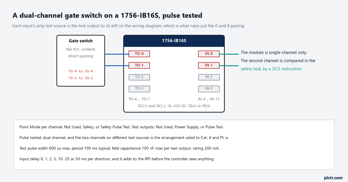
Two contacts, two different test sources. The second channel is not compared on the card; that happens in the safety task.
What the pulse is actually proving
A test output that is doing nothing useful looks exactly like a test output that is working.
With Point Mode set to Safety Pulse Test, the module drops the test output for under 600 µs at a period under 100 ms while the external contact is closed, and watches the input to see the gap arrive. What that catches is a short between the input and 24 V, and a short between two input signal lines — the two failure modes that would otherwise leave an input reading closed with the guard open. It is not a test of the switch, and it is not a test of anything downstream. The fault, when it comes, is declared at the end of the test output pulse rather than at its start, which is worth knowing when you are looking at a trace and trying to decide whether the module or the device reacted first. There is a limit in the specification that the wiring can hit before anything else does: 100 nF of field capacitance per test output. A long shielded run to a remote guard is capable of reaching that, and the symptom is a test pulse that arrives at the input rounded off rather than square.
The card also lets a test output be a plain 24 V supply. Rated 200 mA, and the manual is blunt about the boundary: never use a test output as a safety output.
Where the cross-fault mechanism is set up on the controller side, cross-fault detection between two safety channels covers what the pulses look like on the wire and which wiring defeats them.
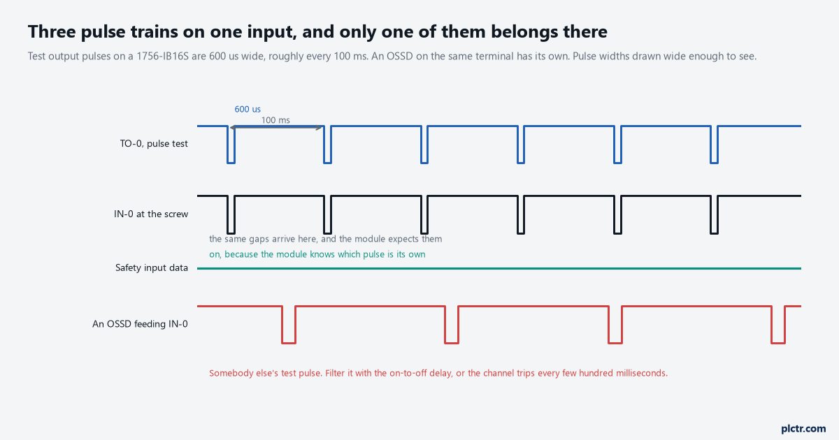
The module recognises its own pulse. It has no way of recognising somebody else’s.
Dual channel is not a setting on this card
Look for a dual-channel option in the module properties and you will not find one.
The 1756-IB16S is single-channel Point Operation Type only, fixed, on every channel. It evaluates each input on its own and reports each one on its own, and the discrepancy between the two contacts of a gate switch is compared in the safety task, by a dual channel instruction — DCS for a stop function, and its relatives for the others. That split is deliberate and it moves the interesting settings out of the module and into the routine: the discrepancy time lives with the instruction, not with the card. It also means the suitability level the card reaches depends on how you use it rather than on what it is. Single channel with Safety Pulse Test is listed up to SIL CL 3, PL d, Category 2; dual channel with Point Mode Safety reaches Category 3; dual channel with Safety Pulse Test, or dual channel with the two channels separated in the loom so one crushed cable cannot take both, is what the table puts at Category 4 and PL e.
The card is also only half of the story on the controller side.
A GuardLogix 5580 without a 1756-L8SP safety partner is rated to SIL CL 2, PL d, Category 3, and only with the partner fitted does the system reach SIL 3 and PL e. The modules are usable either way — the manual says so explicitly — but the number in your safety file is the system’s, not the card’s. For the instruction that does the comparing, moving the same safety function from a 440R relay to GuardLogix covers what the rung replaces, and discrepancy time on a dual-channel safety input covers the number itself.
What OSSD means, and why you do not pulse test one
An OSSD is an output signal switching device, and the name describes a behaviour rather than a component.
What it amounts to is a pair of solid-state outputs pulled up to the supply, which the device itself tests: for a short to the DC supply, a short to DC common, and a short between the two signals. A light curtain has them. So does a non-contact switch of the SensaGuard kind, and so does the safety output of a small configurable relay. The device is already doing to its own outputs what the 1756-IB16S test output would do to a dry contact, which is why configuring that input for Safety Pulse Test is a mistake: two test regimes end up fighting over the same wire, and what the module sees is not its own pulse pattern. Set Point Mode to Safety and let the device’s diagnostics do the work they were certified to do. The remaining problem is the other direction — the module seeing the OSSD’s own test pulse and reading it as the input going to its safe state — and the fix for that is the on-to-off delay. The GuardLogix safety reference manual says the same thing in the same words: the pulse duration is measured in microseconds, the safety input can still detect it as a transition, and the smallest configurable millisecond delay is usually enough to filter it.
One millisecond is usually enough. Fifty is somebody guessing.
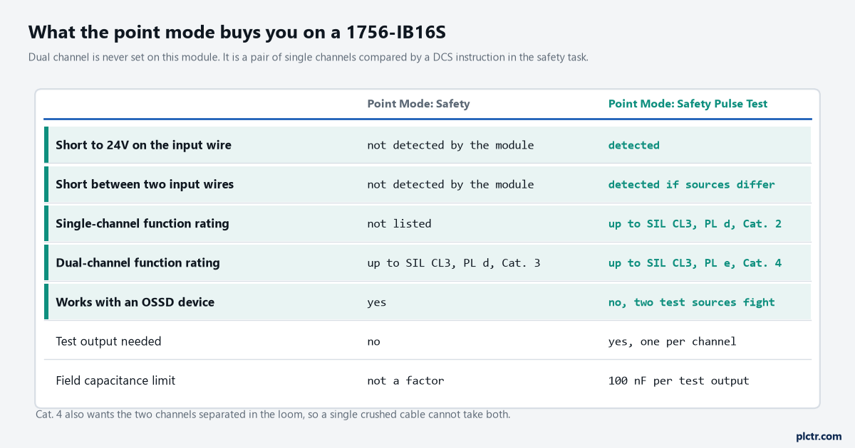
The row that decides most installations is the OSSD one. A pulse-tested input and a pulse-testing device do not belong on the same terminal.
The delay you add, and the delay already there
Every filter you configure comes out of the machine’s stopping distance.
The off-to-on and on-to-off delays are selectable per channel from a fixed list — 0, 1, 2, 5, 10, 20 or 50 ms — and they work by holding the state: during an off-to-on delay the input is still treated as logic 0, during an on-to-off delay it is still treated as logic 1. On top of that sits the RPI, which is settable from 2 to 500 ms, and the manual’s own worked example is the one to remember: at a 10 ms RPI with a 2 ms input delay, a change at the screw can take up to 12 ms to appear at the controller. The specification puts the module’s own screw-to-backplane input delay at 6 ms maximum with a 2 ms RPI, before any filter you add. None of those numbers are the reaction time of the safety function, which also has the device, the safety task period, the output module and the contactor in it, and the safety reference manual says plainly that configured delays have to be counted in.
Add them up on paper once. The number is always larger than people expect.
When it faults on its own
Two conditions recover without anybody going to the panel, and one does not.
Field power loss faults every point on the module at once, and the only correction is to put field power back; recovery can take up to a second on top of the Input Error Latch Time. A short circuit or an overload on a test output — the specification calls out overload current above 0.7 A — faults and turns that output off, and after the short is removed it recovers in whichever is longer, ten seconds or the Input Error Latch Time. How the fault status clears depends on a module-level choice: with Latch Fault until reset via output tag enabled, the channel holds the indication until it sees a rising edge on ResetFault in the consume assembly, and with it disabled, which is the default, the channel holds for one second and then clears itself once the input is low. Neither of those is a safety function. They are diagnostics, and the status indicators are explicitly not to be used for safety operations.
A few installation facts worth checking before the card is ordered rather than after: it needs a Series C ControlLogix chassis, it takes a 1756-TBCHS or 1756-TBS6HS removable terminal block, the cage clamp is 0.5 N·m, and the whole thing draws 280 mA from the 5.1 V backplane with up to 1.8 A of field power behind it.
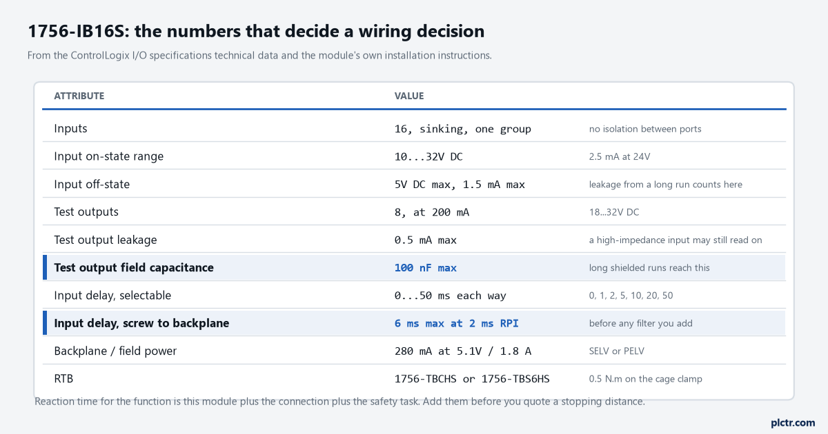
The field capacitance limit and the screw-to-backplane delay are the two that decide whether a long run to a remote guard works as drawn.
Next step: open the module properties on a card that is already in service and write down the Point Mode of every used channel alongside what is actually wired to it. Any OSSD device sitting on a channel set to Safety Pulse Test is a nuisance trip waiting for a quiet shift, and any dual-channel device landed eight channels apart is a cross-fault the card cannot see. If you are still deciding whether this card belongs in the design at all, a safety relay or a safety PLC covers where the crossover sits.