Inputs I0 and I1 on a 1791ES-IB8XOBV4 went solid red one afternoon with the guard closed, and the DCS instruction in the GuardLogix 5580 behind them has held Input Status false ever since. The guard switch on the infeed has two NC contacts in one four-core cable, the cable was crushed where it enters the duct, and the copper of the two supply cores has been touching for a month, so the machine has been running on the bypass key while somebody argued that the module was faulty. It was not. Cross-fault detection found a short between two safety channels with the guard closed and nobody near it, which is the one thing the two test outputs on the front of it exist to do. Here is how that detection works, the wiring that switches it off without anyone noticing, and what the same short looks like when it is found the slow way, on the day a person opens the guard.
The short answer: each channel is sourced from its own test output, each test output carries a different pulse, and an input that sees the wrong pulse is shorted to something.
What a test output actually puts on the wire
A test output is not a 24 V supply with a fancy name, although it will work as one if you configure it that way.
Configured as Pulse Test, T0 drives the wire high and drops it low for 500 µs every 150 ms on the 1791ES, 525 µs every 144 ms on a 1734-IB8S, and the module watches for that dip to arrive at the input the test output is assigned to. The Guard I/O manual lists what the dip lets it see: a short between an input line and the positive supply, because the dip never arrives, and a short between two input lines, because a dip arrives that this input’s own source did not send. T0 and T1 pulse at different moments, so a wire sourced by T0 shows T0’s pattern and nothing else. Bridge it to a wire sourced by T1 and the input on the far end sees both patterns, fails its pulse check inside one period, and the module drops the input data and the individual input status to zero and holds them there for the Input Error Latch Time. The status LED goes solid red on the input with the fault and flashing red on its partner. All of that happens with the guard closed and the contacts closed. No demand, no discrepancy timer, no person; the module simply knows that a wire is where it should not be.
Same-source wiring gives you none of that, and the cable looks identical from the outside.
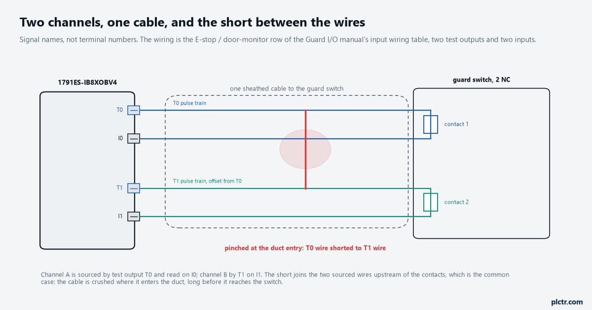
The short joins the two wires that carry the test pulses, upstream of the contacts. That is the common place for it: the cable is crushed at the duct, a long way from the switch.
What cross-fault detection sees, and what it does not
Two drawings of the same four seconds, one with the wiring the manual shows and one with the wiring that gets built when there are not enough test outputs to go round.
With separate sources, I1 is fed by T1 through the short from T0 as well, so its trace carries both dip patterns and the module faults it on the first pulse that does not belong. With both channels on T0 the pulses on the two wires are identical, the short joins two wires that already carry the same pattern, and there is nothing for the module to compare; it stays quiet until the guard opens. Then contact 2 opens and I1 should go to zero, but I1 is still fed through the short from the wire on the other side of contact 1, which is still closed for the few milliseconds of stagger and then open. Channel A goes to the safe state, channel B does not, the discrepancy time runs out, and the DCS reports Fault Code 16#4001 – channel A safe, channel B active past the discrepancy time – which reads as a slow contact block, a worn actuator or a bad discrepancy setting, and sends the technician to the switch when the fault is at the duct. A short downstream of the contacts, between the two wires that return to I0 and I1, behaves the same way on either wiring: invisible until a demand, then a discrepancy. That is the honest limit of pulse testing, and the reason a two-channel device is not two chances but one chance plus a diagnostic.
The manual gives a number for the difference. Its wiring table rates a single-channel pulse-tested device at Category 2 and PL d maximum, and the same device on two inputs with two test outputs at Category 4 and PL e maximum; those are Rockwell’s entries for the module, not the standard, and what Category 4 requires is defined in ISO 13849-1, which is not reproduced here.
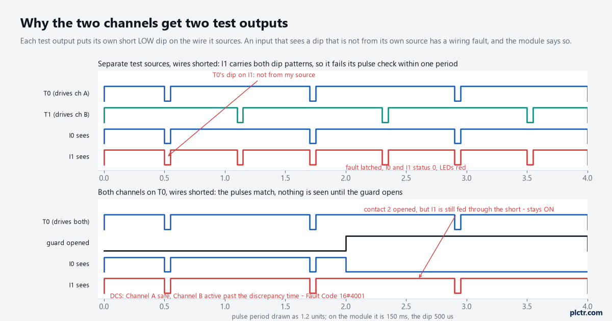
Top: the module finds the short at once, with the guard closed. Bottom: the same short, shared source, found by a person opening the guard and reported as a discrepancy.
The wiring that switches the detection off
Three ways it gets built, and all three pass a functional test on commissioning day.
The first is both contacts fed from T0 because the drawing was copied from a relay panel, where one supply wire to a guard switch is normal and the relay’s cross-fault detection works differently. The second is one contact fed from T0 and the other from a 24 V rail because the eight test outputs on the module had run out and somebody needed the door to work by Friday; the rail-fed channel has no pulse to check, so a short to 24 V on that wire is invisible and a short to the T0 wire is seen from the T0 side only. The third is the subtle one: both test sources correctly assigned in the wiring and the wrong one selected in the configuration, so I1 is physically on T1 but configured with Test Source T0, and the module reports pulse test failures on I1 with nothing wrong in the cable at all. The Guard I/O manual has a footnote for exactly that case – if the incorrect test source is entered, the result is pulse test failures on that input circuit – and it is the first thing to check when an input faults straight after a download and the wiring has not been touched.
A fourth defeats it differently: configuring the input pair as Dual-channel Equivalent on the module with a discrepancy time, and also using a DCS. The manual’s footnote says configuring discrepancy time on the module masks input-inconsistent faults from the safety instructions, so the DCS never sees 16#40xx; the pulse test still works, but the discrepancy story above happens inside the module and the controller reads a matched pair. The discrepancy time article is the long version of which of the two settings the instruction is really looking at.
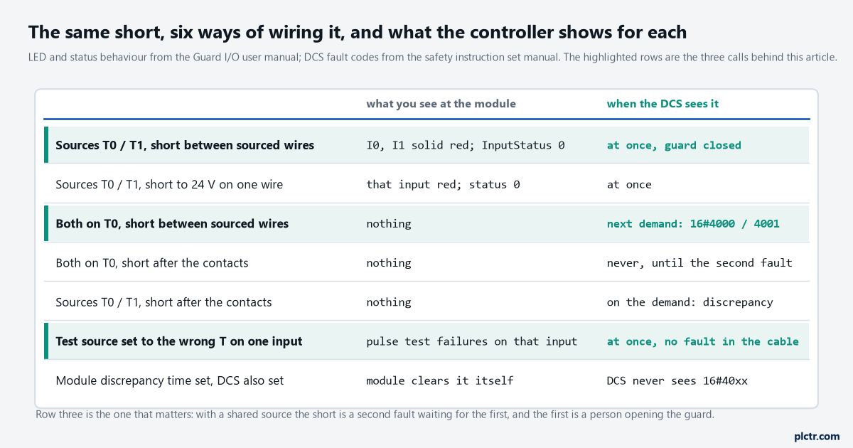
Row one is the manual’s wiring. Row three is the one that runs for a year and then reports a discrepancy. Row six is a configuration error that looks like a cable fault.
What to set, on the module and in the DCS
The settings are short, and every one of them has a name in the manual’s input parameter table.
Each of the two inputs gets Point Mode Safety Pulse Test, and each gets its own Test Source – Test Output 0 for I0, Test Output 1 for I1 – which must be the test output physically wired to that contact and not merely a different number. Point Operation Type stays Single Channel so the DCS does the pairing and reports the discrepancy with a code. Test Output 0 and 1 Mode are Pulse Test, not Power Supply; a test output set to Power Supply is a 24 V source with no dip, and an input assigned to it has nothing to check against. Input Error Latch Time is left at 1000 ms so a pulse-test failure that lasts a few milliseconds is held long enough for the safety task to read the status bit. In the DCS, Input Status takes the module’s combined input status tag, so a pulse-test fault on either channel drops the instruction into fault code 16#20 – Input Status transitioned from on to off while the instruction was executing – before any discrepancy timer has a chance to run. That is the code you want to see for a short: it says the module found a wiring fault, not that the contacts disagreed.
Two channels, two test outputs, one DCS. The third test output goes to the reset button, pulse-tested as well, so a jumper across it is seen for what it is.
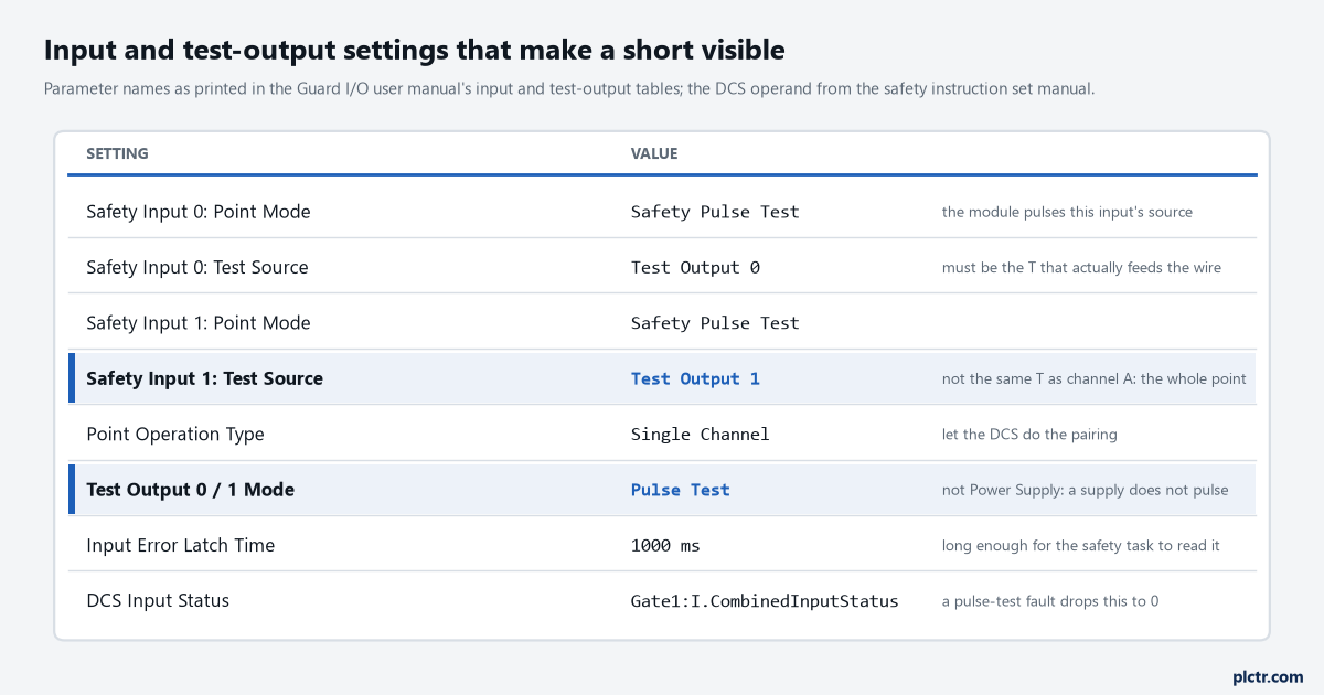
Parameter names as the Guard I/O manual prints them. The two highlighted rows are the ones that get set to the same value on both channels by mistake.
The Siemens equivalent, and where its detail lives
An ET 200SP F-DI does the same job with its own sensor supplies: each channel of a 1oo2 pair is fed from a supply the module can test, and a short between the wires or to 24 V is a channel fault. The SIMATIC Safety manual lists short-circuit among the channel faults that passivate a channel – the channel value goes to the fail-safe 0 and the value status drops – and the Siemens programming guideline’s glossary describes the cross-circuit case in one line worth keeping: a sheathed cable being pinched, and a two-channel E-stop circuit that then fails to trip when only one NC contact is faulty, which it calls the secondary error. The exact parameter names for the sensor supply and the short-circuit test, and which channels pair for 1oo2 evaluation, are in the F-DI 8x24VDC HF equipment manual, which I could not open for this article; the SIMATIC Safety manual is the source for everything above, and it sends you to the module manual for the rest. What passivation does to the channel afterwards, and why it stays at zero until somebody acknowledges, is its own article.
The F-DI finds the short with the door closed, the same as the Guard I/O module, and for the same reason.
Next step
Open the module properties and read the Test Source on each safety input against the drawing, then follow the two wires to the switch with a meter and confirm that T0 really lands on contact 1 and T1 on contact 2. If both contacts share a source, the fix is one wire and one configuration change, and it is worth doing before the cable is crushed rather than after. If an input is red now with the guard closed, the module has already found the short; ring the cores against each other at the switch end with the module powered down and look at the duct entry first. The terminal-by-terminal wiring that this article assumes is in dual-channel E-stop wiring on GuardLogix, and the output-side pulse that does the same job on a contactor coil is in test pulses on a safety output.
A short found with the guard closed is a diagnostic. A short found when the guard opens is a near miss.