A guard door wired to a standard input, an XIC in MainRoutine and an OTE dropping the drive is an interlock. It is not a PLC safety interlock. It will pass a works test and it will still let the machine run with the door open the day the input card welds a channel shut. This walkthrough builds the same door and E-stop function properly on GuardLogix, with the wiring, the instruction settings, the discrepancy time and the reset rule that people get wrong.
This describes what the hardware and the instructions do. Nobody validates a safety function from an article. The risk assessment, the performance level target and the verification belong to whoever signs the file.
Standard interlock or safety function
Answer this before you pick hardware.
| Question | Standard PLC interlock | Safety-rated function |
|---|---|---|
| What is it protecting | Product, machine, sequence | A person’s hands or life |
| Single fault behaviour | Unknown, often stays energised | Must go to a safe state |
| Typical target | None stated | PLd or PLe to ISO 13849-1, SIL 2 or SIL 3 to IEC 62061 |
| Where the logic lives | MainTask | Safety Task, ladder only |
| Hardware | 1756-IB16, any controller | 1756-L8xES or 5069-L3xxERS2, safety I/O |
| Who may change it | Anyone with a download | Anyone, but the safety signature breaks and you have to say so |
Stock rotation, a full accumulation table, a valve sequence: standard logic is right for all of them. A light curtain in front of a press is not a standard interlock, whatever the machine builder put in the panel.
What the example uses
| Item | This example |
|---|---|
| Controller | 1756-L83ES GuardLogix 5580, firmware 33, Studio 5000 v33 with the safety option |
| Safety input | 1734-IB8S POINT Guard I/O on a 1734-AENTR adapter |
| Safety output | 1734-OB8S, two channels to the contactor coils |
| Devices | E-stop with two normally closed contacts, guard door switch with two channels, blue reset push button |
| Target | PLd, category 3 architecture, single fault tolerant with detection |
| Actuators | Two contactors in series, auxiliary contacts back to a safety input for feedback |
Step 1: Wire the channels so a short is visible
A category 3 dual-channel input only reaches its performance level if a short between the two channels is detected. That is what test pulses are for.
- Take the two test sources on the 1734-IB8S,
T0andT1, into the two E-stop contacts. Do not feed both contacts from the same 24V rail, and do not feed them both from the same test source. - Bring contact 1 back to input point 0, contact 2 back to input point 1.
- Run both channels in the same multicore only if the cable is protected. A crushed cable that shorts channel A to channel B is exactly the fault the test pulses catch, and the module will fault the point rather than sit there looking healthy.
- Wire the reset push button to a standard or safety input, your choice, but put it where the operator can see the whole guarded area. A reset button behind the machine is a design fault, not a wiring detail.
- Feed the contactor auxiliary contacts, mirror contacts if you have them, back to a safety input for the output feedback loop.
Step 2: Configure the safety I/O
- Add the 1734-AENTR under the Ethernet port, then the 1734-IB8S in its slot. The safety network number is generated when you add the module. Write it down. It is part of the connection identity, and replacing a module without setting it will not connect.
- Open the module properties, go to the input configuration, and set points 0 and 1 to use test outputs
T0andT1. This is what turns on pulse testing. - Set the point operation type to dual channel, equivalent. Complementary is for devices where one contact is NC and the other is NO.
- Set the discrepancy time in the DCS instruction, not on the module. 500 ms handles a worn E-stop where one contact breaks before the other. Do not set it to several seconds because a device keeps faulting: a device that cannot make 500 ms is worn out. Leave the module’s own Input Configuration discrepancy time at zero. Publication 1791ES-UM001 states on page 89 that configuring a discrepancy time on the safety I/O module masks input inconsistent faults from the GuardLogix safety instructions, which is exactly the fault text this walkthrough later puts on the HMI. Set it in both places and the electrician loses the channel name that makes the bad contact findable.
- Set the safety connection RPI. The safety task period must be longer than the RPI and the whole reaction time budget has to include it. Ten to twenty milliseconds is normal for a discrete safety input.
Step 3: Write the safety routine
The Safety Task is ladder only. No Structured Text, no SFC. Instructions come from the safety set, and the ones you need for a door and an E-stop are the dual channel input instructions.
SafetyTask, 20 ms periodic, program Zone1_Safety, routine S_EStop

Rung 0 ------------------------------------------------------
  DCS    Dual Channel Input Stop              (E-stop)
    Safety Function      EStop_Zone1
    Channel A            EStop_In:I.Pt00Data
    Channel B            EStop_In:I.Pt01Data
    Input Type           Equivalent - Active High
    Discrepancy Time     500 ms
    Restart Type         Manual
    Cold Start Type      Manual
    Reset                Reset_In:I.Pt04Data
    Outputs              O1 -> EStop_Zone1_OK
                         FP -> EStop_Zone1_Fault

Rung 1 ------------------------------------------------------
  DCS    Dual Channel Input Stop              (guard door)
    Safety Function      Door_Zone1
    Channel A            Door_In:I.Pt02Data
    Channel B            Door_In:I.Pt03Data
    Input Type           Equivalent - Active High
    Discrepancy Time     500 ms
    Restart Type         Manual
    Cold Start Type      Manual
    Reset                Reset_In:I.Pt04Data
    Outputs              O1 -> Door_Zone1_Closed
                         FP -> Door_Zone1_Fault

Rung 2 ------------------------------------------------------
  EStop_Zone1_OK   Door_Zone1_Closed   Zone1_Fault
  ------] [-------------] [----------------]/[---------
                                                   CROUT
                                              Out1 -> K1
                                              Out2 -> K2
                                              Feedback -> K1K2_Aux
                                              Feedback Delay 100 ms
DCS is the instruction for any dual-channel device whose job is to stop the machine, an E-stop, a light curtain or a guard door alike, which is why both rungs above use it with the same Restart Type and Cold Start Type settings. CROUT drives the two contactor channels and watches the feedback contacts, so a welded contactor faults the output rather than hiding.
The FP fault outputs are not decoration. Bring them into the standard task with a safety tag mapping and put them on the HMI with the channel name. An electrician who can see “E-stop zone 1, channel discrepancy” finds the bad contact in five minutes instead of two hours.
Step 4: The reset rule
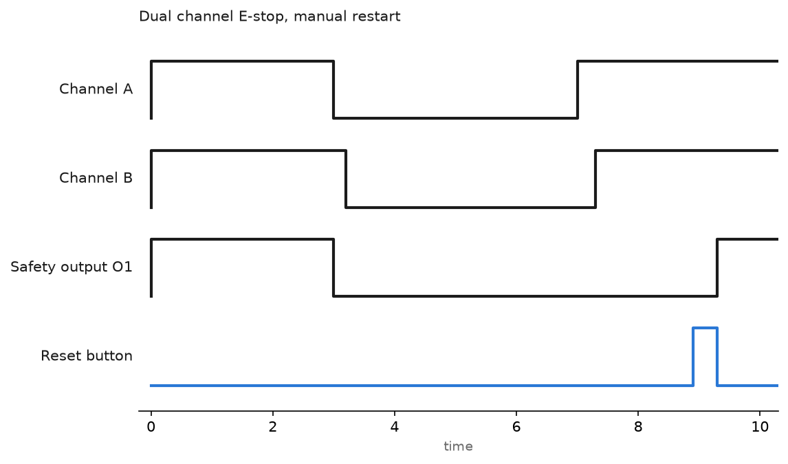
The safety output must never come back on its own. When the E-stop is released or the door is closed, nothing happens until someone presses and releases the reset button. That is what Restart Type Manual means, and it is why the reset is an edge, not a level.
Watch the chart above. Channel A opens, channel B follows 200 ms later, the output drops immediately. Releasing the E-stop at the 7 second mark does not restart the machine. The output only returns after the reset pulse.
The Cold Start Type setting is the same rule applied to a power up. Leave it on Manual. With it on Automatic, a controller that powers up with the guards closed enables the safety output straight away, and a machine that starts by itself after a power dip is how people get hurt.
The same function on an S7-1500F
- Use an F-CPU, for example a CPU 1516F-3 PN/DP, with an F-DI module such as the 6ES7136-6BA01 for ET 200SP. In the module properties set the channels to 1oo2 evaluation with a discrepancy time, and enable the internal sensor supply test.
- In the safety program, call
ESTOP1from the F-blocks. ItsE_STOPinput takes the evaluated dual channel result,ACK_NECset to 1 forces a manual acknowledge, andACKtakes the reset button. - For a guard door use
SFDOOR, which handles the open and closed states plus the acknowledge. - Use
FDBACKfor contactor feedback, the equivalent ofCROUT. - After compiling, TIA Portal shows a safety program signature. Any change to the F-program changes it, the same way the Logix safety signature does.
Field notes
The cross fault that hid for a year. A door switch on a packaging cell had both channels running through one crimp lug because the panel builder had run out of terminals. Channels A and B were bridged. For a year it worked perfectly, because both channels always agreed. It only showed up when we moved the station to pulse-tested inputs and the module faulted the point within a second. The old arrangement had been a single channel dressed as dual.
Discrepancy time turned up to make an alarm go away. A shift electrician was tired of an E-stop faulting once a week and raised the discrepancy time from 500 ms to 3 seconds. The fault stopped. The real cause was a mushroom head that had been hit sideways so many times that one contact block was hanging. Three seconds of disagreement between two channels of an E-stop is not a tuning parameter, it is a broken device. Replace the contact block and put the time back.
The forgotten safety signature. An integrator went online to change a standard rung, and Studio 5000 deleted the safety signature because the safety task was in a state that did not allow the edit. Nobody noticed. The machine ran for three months with an unsigned safety program, which meant nothing had been verified against a known copy. Print the signature ID and date, keep it with the machine file, and check it during the annual inspection. It takes thirty seconds online.
Standard logic bypassing the reset. A drive stopped by a safety contactor also had a standard run bit from MainTask, and someone latched that bit for a coast-to-stop feature. The contactor was never defeated, but the drive restarted the instant it closed, before the operator touched anything. The reset rule has to reach the machine start sequence, not only the safety output.
Frequently asked questions
Can I do a safety interlock on a standard ControlLogix?
You can build logic that behaves like an interlock. You cannot claim a performance level for it, because nothing in a standard controller detects a stuck input, a welded output or its own failure. For guarding, use a safety controller or a safety relay.
Do I need dual channel for everything?
No. Single channel with a tested output can reach PLc on some architectures. The determination comes from your risk assessment, not from a preference. What you must not do is wire single channel and describe it as category 3.
How long is the reaction time of the whole function?
Add the input filter, the safety connection RPI, the safety task period, the output connection RPI and the contactor drop-out time. Rockwell publishes a reaction time worksheet for the GuardLogix families. Do the arithmetic before you quote a stopping distance.
Can I reuse my safety logic across machines?
Yes, with safety Add-On Instructions. They have their own signature and instruction signature so you can prove the block has not changed. The mechanics are in Safety Add-On Instructions and the general build process in Add-On Instructions.
Where does IEC 61508 fit?
It is the parent standard the machinery and process sector standards derive from. Background is in IEC 61508, IEC 61511, EN 50126 and related standards.
Next step
Bring the safety fault bits into the standard program and put them somewhere an electrician will see them at 2am. The mapping and diagnostics work is the same pattern used in PLC controller fault routine, and packaging a tested safety function into a reusable block is covered in Studio 5000 Add-On Instructions. An interlock that must stay tripped on an unmanned site, where the only reset is a push button on the pad, is worked through in wellhead ESD logic and RTU polling.