A 1756-IB16 is a sinking input module, so it wants PNP sensors, and a stock room full of NPN sensors means a sourcing card or a row of interposing relays nobody quoted. Polarity is the decision on PLC I/O modules you cannot fix after the order goes out; the point count and the analog jumper nobody drew you still can. This walkthrough is the decision order I use on a ControlLogix rack and a CompactLogix 5069 bank: type, polarity, terminal, keying, then scaling. ET 200SP differences are called out where they matter.
What is on the bench for this example
| Item | Detail |
|---|---|
| Controller | 1756-L83E in slot 0, firmware 33.011, Studio 5000 v33 |
| Discrete input | 1756-IB16, 16 points, 24V DC, sinking |
| Discrete output | 1756-OB16E, 16 points, 24V DC, sourcing, electronically protected |
| Analog input | 1756-IF8, 8 channels, current or voltage per channel |
| Remote bank | 5069-IB16 and 5069-OB16 on a 5069-AEN2TR adapter |
| Siemens side | ET 200SP, DI 8x24VDC ST and AI 4xI ST on an IM 155-6 PN |
Start with the four kinds of point
Discrete input reads a contact or a sensor that is on or off. Discrete output drives a coil, a lamp or a relay. Analog input reads a continuous signal, usually 4-20 mA, 0-10V or an RTD. Analog output sends 4-20 mA to a valve positioner or a drive speed reference.
Count the points from the schematic, then add twenty percent spare. Spare points are cheap now and expensive six months from now.
Get sinking and sourcing right before the order goes out
This is the decision that ruins schedules. It comes down to which side of the load pushes the current.
- A PNP sensor switches the positive rail onto its output wire. It sources, so it needs an input module that sinks.
- An NPN sensor pulls its output down to 0V. It sinks, so it needs an input module that sources.
The 1756-IB16 is a sinking input module, so it wants PNP sensors, which is what most machine builders ship. The 1756-IB16D adds per-point diagnostics for open wire and short circuit. If your sensor stock is NPN, you need a sourcing input card or a row of interposing relays.
On the output side the 1756-OB16E sources 24V into the load and the load returns to 0V. It is electronically protected, so a shorted output shuts itself down and sets a fault bit instead of taking out a fuse. A sinking output module switches the 0V side instead and is the odd one out in most panels.
ET 200SP DI modules with the ST designation are sinking inputs for PNP sensors, same as the 1756-IB16.
Add the module, then set RPI and keying
- Right-click 1756 Backplane under I/O Configuration, choose New Module.
- Filter on the catalog number, select 1756-IB16, click Create.
- Name it after the panel location, not the signal.
Panel1_DI_S2survives a rewire.Conveyor_Startsdoes not. - Set Slot to the physical position, counted from zero at the left of the chassis.
- On the Connection tab, leave RPI at 20 ms for discrete I/O. The module still catches fast events in hardware. RPI only sets how often that data reaches the controller.
- Set Electronic Keying to Compatible Module unless you are on a validated system that requires Exact Match.
For a full pass through that dialog, including drives and remote adapters, see adding a new module in Logix Designer. If the card is missing from the list at step 2, the EDS file is not installed and the fix is in EDS file installation via RSLinx.
RPI is not free. Eight analog cards at 5 ms cost far more controller and backplane time than the same eight at 100 ms, and a PID loop on a 250 ms task cannot use the difference.
Keying decides what happens when somebody swaps a card at three in the morning. Exact Match rejects a module whose revision differs by one digit. Compatible Module accepts the same or a newer revision of the same catalog number. Disabled accepts anything that fits the connection, which is how a 1756-IF8 ends up answering for a project that wanted a 1756-IF16.
Read the module fault code instead of guessing
When a module is faulted, open its properties and read the Connection tab. The code comes back as a hex value.
| Code | What it usually means | First thing to try |
|---|---|---|
| 16#0010 | Configuration rejected, or the device is in a conflicting state | Check the slot, and that no second controller owns the module |
| 16#0109 | Connection size mismatch | Project expects a different data format |
| 16#0114 | Keying, wrong catalog number in the slot | Read the label, fix the project |
| 16#0116 | Keying, revision mismatch | Set Compatible Module, or flash the card |
| 16#0203 | Connection timed out | Cable, switch port, adapter power |
The pattern worth memorising: 011x codes are an argument about what the module is, while 0203 is a transport problem and has nothing to do with your configuration. A longer list is in Allen-Bradley PLC I/O faults, causes and solutions.
Wire the 4-20 mA loop the way the module expects it
A 2-wire transmitter has no supply of its own. It modulates the current in the loop that powers it. A 4-wire transmitter has its own supply and drives the current itself. The 1756-IF8 takes both, but the jumpering changes.
- Set the channel to current mode in module properties. The sense resistor is inside the module, so do not add a 250 ohm resistor at the terminal block.
- For a 2-wire transmitter, run 24V positive to the transmitter plus terminal, bring the transmitter minus back to the channel input, and fit the jumper from that channel return to the module return terminal shown in 1756-IN005.
- For a 4-wire transmitter, leave the loop supply leg out and land only the signal pair.
- Ground the shield at the panel end only. Both ends gives you a ground loop, which shows up as a slow drift on hot afternoons.
- Before you trust the tag, break the loop and put a meter in series. A calibrated 12.00 mA that reads 50 percent in the tag means the whole chain is right.
Turn raw counts into engineering units
The count range depends on the platform, which is why copied scaling code produces wrong readings so reliably.
| Platform | 4-20 mA maps to | Notes |
|---|---|---|
| 1756-IF8 and 5069-IF8 | Scaled in module properties | Enter low and high signal plus engineering units, the tag arrives scaled |
| SLC 500 1746-NI4 | 3277 to 16384 | Classic SCP territory |
| MicroLogix 1762-IF4 | 0 to 4095 at 12 bit | 4 mA lands on 819 counts |
| S7-1500 analog input | 5530 to 27648 | 0 to 20 mA spans 0 to 27648, overrange goes higher |
When the module will not scale for you, do the arithmetic once, in one routine, and give the result a tag name that says what it is:
(* Structured Text, 4-20 mA on a 12 bit card, sensor range 0 to 250 bar *)
(* 819 counts = 4 mA = 0 bar, 4095 counts = 20 mA = 250 bar *)

IF Raw_Pressure < 700 THEN
    Pressure_Fault := 1;              (* under 3.4 mA, treat as a broken loop *)
ELSIF Raw_Pressure > 4000 THEN
    Pressure_Fault := 1;              (* over 19.5 mA, sensor out of range *)
ELSE
    Pressure_Fault := 0;
END_IF;

Pressure_bar := (Raw_Pressure - 819.0) * (250.0 / (4095.0 - 819.0));

(* Same sensor on an S7-1500 *)
(* Pressure_bar := (INT_TO_REAL(Raw) - 5530.0) * (250.0 / (27648.0 - 5530.0)); *)
The broken loop test is the part people skip. A signal that collapses to 0 mA scales to a negative pressure, and a negative pressure handed to a PID loop drives the output hard against a limit. Catch it at the scaling and let the alarm instruction do the rest, as in PLC analog alarm ALMA and analog alarm timing diagrams.
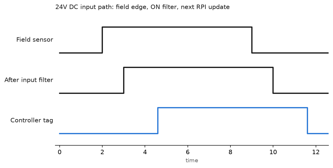
That is why a fast sensor still looks slow in the program. The edge waits out the input filter, then the next RPI, then the next scan. With a 20 ms RPI and a 10 ms task, worst case from contact to logic is around 31 ms. Fine for a conveyor, useless for a registration mark, which is what high speed counter modules exist for.
Field notes
The floating input that alarmed every night. A 1756-IF8 had three spare channels with nothing landed on them, left in voltage mode. They drifted with cabinet temperature and tripped a high alarm on a tag nobody used, which buried the real events. Fix took two minutes: put unused channels in current mode, or jumper the input to return.
Output on in the program, nothing at the solenoid. An older 1756-OB16 with a field-side fuse in the panel. The fuse had opened two shifts earlier from a shorted valve coil, the output tag still showed 1, and a technician spent an hour in the ladder. The 1756-OB16E in the next slot hit the same short a month later and reported it in Local:4:I.Fault.3 within a second.
Same card, different series, rack down all Sunday. A spare 1756-IF8 series A went in for a failed series B. The project had Exact Match keying, the module answered 16#0116, and the line stayed down until somebody drove in with a laptop.
Slices on the wrong potential group. On an ET 200SP rail, an extra DI module went in after a light blue base unit. That base started a new potential group fed from a supply switched by the safety relay, so those eight inputs died every time the guard door opened.
Frequently asked questions
How do I tell whether a sensor is PNP or NPN?
Read the label or the datasheet. If you have neither, power it on the bench and meter from the output wire to 0V with the target in front of it. A PNP output sits at 24V, an NPN output near 0V.
Can I mix 24V DC and 120V AC on one module?
No. A module is one voltage family. You can mix module types across a 1756 chassis, but keep AC cards away from analog cards and run the wiring in separate ducts.
What RPI should I use for analog inputs?
Set it to roughly a quarter of the period of the task that consumes the data, then leave it. A 250 ms PID loop gains nothing from a 5 ms analog update.
Why does my input tag flicker?
Either the device is genuinely bouncing or the input filter is faster than the contact. On 1756 DC input modules the on and off filter times are set per module group in module properties. Raising the off filter to 9 ms kills most mechanical bounce.
Next step
With the cards in and the signals scaled, the next job is alarming the analog values. That starts with PLC analog alarm ALMA. If a device is still missing from the New Module dialog, work through the Allen-Bradley EDS file download first.