Hardwired or Networked Safe Torque Off on a Kinetix 5700: What Each One Needs
The drive is in the GuardLogix I/O tree, the safety connection shows as running, SO.SafeTorqueOff is high, and the axis still refuses to enable. Read the STO fault type over an explicit message and it comes back 104: hardwired input in network mode. The bypass jumpers are still in the safety connector plug from the day the machine was first turned over, and until they come out the networked mode is not going to command anything.
Both modes on a Kinetix 5700 end at the same gate driver and both are rated the same way. What differs is what has to exist beforehand, who can command the stop, what happens the day somebody replaces the drive, and how you tell which mode a drive is actually sitting in.
The connector, the pins and the jumpers are covered in the article on wiring safe torque off on a Kinetix 5700. This one is about the choice.
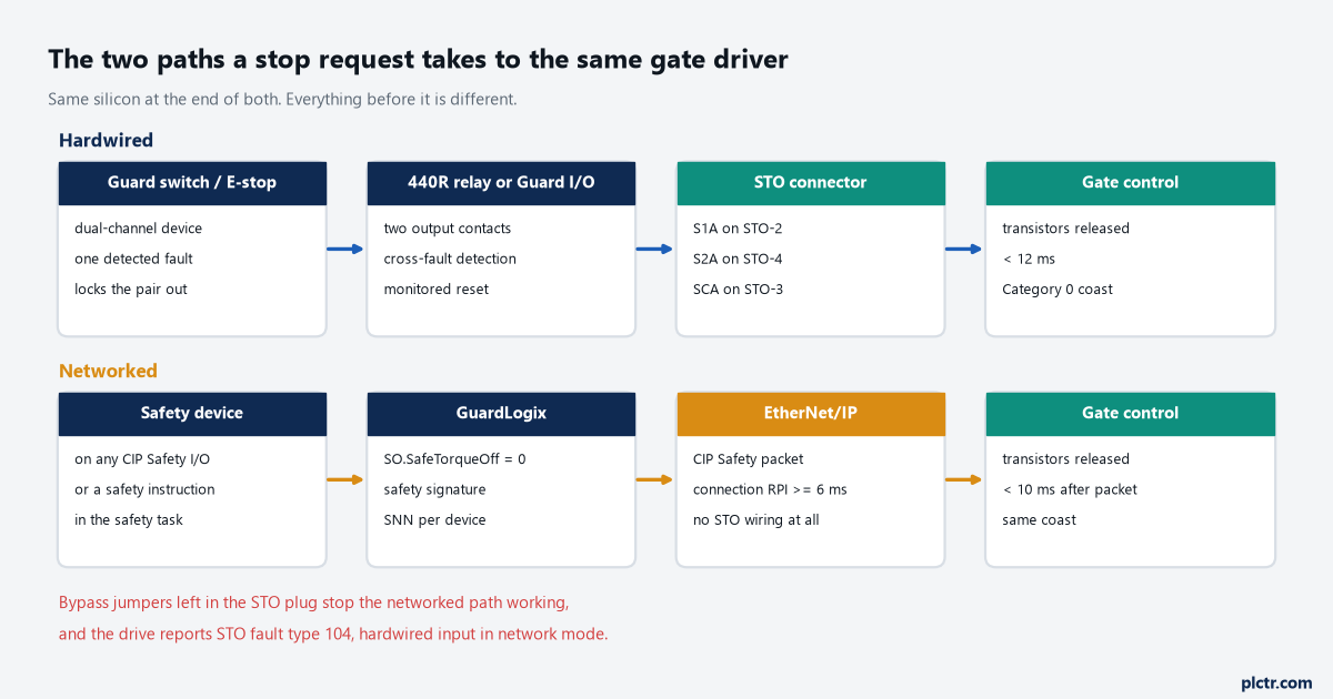
Same silicon at the end of both paths. Everything upstream of the gate driver is a different set of things that have to be right.
Which one you already have
Out of the box, every Kinetix 5700 inverter is in Hardwired STO mode.
That is not a default you can ignore, because the manual attaches a condition to the other mode: a drive can be used in Integrated STO mode only after a Motion and Safety or a Safety Only connection has been established at least once from the Logix Designer application. A brand-new 2198-S086-ERS4 out of the carton will take 24 V on its safety inputs and behave exactly as a hardwired drive, whatever the intention of the panel drawing. On a 2198-xxxx-ERS4 or an ERS3 of series B or later, the mode is a pull-down — Safety Application, Hardwired or Networked, in the Module Definition dialog under the module’s General category. On an ERS3 of series A there is no such pull-down; the drive falls into integrated mode when the connection is applied, and getting it back takes a Reset Ownership.
Read the mode rather than assuming it. The axis tag AxisSafetyState carries it, and so does a Safety Supervisor read.
What the networked mode needs before it works at all
Four things, and the bypass jumpers are the one that gets forgotten.
The drive has to be in the safety controller’s I/O configuration, the connection has to be Safety Only or Motion and Safety rather than Motion Only, the STO bypass jumper wires have to be out of the plug, and the safety task has to own a valid configuration with a safety network number behind it. Miss the jumpers and the symptom is the one above: a drive that looks correctly configured, a safety connection that looks healthy, and fault type 104 waiting behind an explicit message to class 0x5A, attribute 0x108, on the axis instance. That message is worth putting in the machine’s diagnostic routine once rather than rediscovering it: service code 0x0E, class 0x5A, instance 1 or 2 for the inverter axis, attribute 0x108, data type SINT, where 1 is no fault, 3 is a circuit error and 104 is the hardwired-input case.
The safety supervisor object is the other half of the same diagnostic. One per drive, so on a dual-axis inverter both axes report the same value.
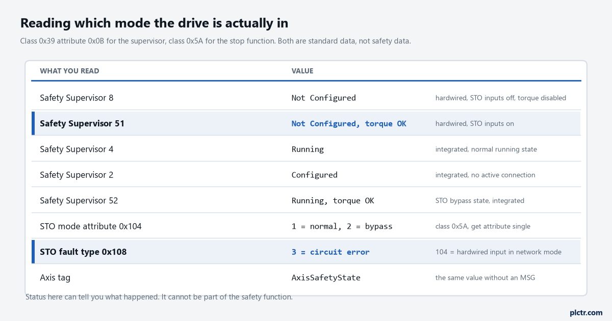
Every value here is standard data. It is good enough to tell you what happened and not good enough to be part of the safety function.
The bit that is high when torque is allowed
Anyone writing the safety routine for the first time trips over this once.
SO.SafeTorqueOff is not a request to remove torque. In the safety output assembly a 0 means disable permit and a 1 means permit torque, so the tag sits high while the machine is running and is driven low to bring the safe torque off function on. Under Logix Designer version 31 and later the name changes when Motion Safety in the Module Definition is set to Safe Stop Only – No Feedback, at which point the same bit is SO.STOOutput and the reset is SO.ResetRequest rather than SO.Reset. Coming back out of a fault has an order to it that the manual states twice: SO.SafeTorqueOff has to transition from 0 to 1 first, and only then does a 0 to 1 transition of SO.Reset clear the STO fault. Do it the other way round and nothing happens. On the input side, SI.TorqueDisabled reads 1 when torque is disabled, SI.SafetyFault reads 1 when an STO fault is present, and SI.ResetRequired tells you a reset is expected — and only the data in those assembly tables travels with SIL 3 integrity, which is exactly why the axis-tag view of the same information is not a substitute.
One more thing that surprises people on a dual-axis inverter: any STO fault puts every axis of that inverter into the faulted state.
Clearing Axis.SafetyFault afterwards still needs an MAFR from the motion side.
Reaction times that are not in the same units
Twelve milliseconds against ten looks like the networked mode wins. It does not, quite.
The hardwired figure is a complete answer: de-energise a safety input, and in under 12 ms the output transistors are off. The networked figure is measured from a different starting line — the drive’s STO reaction time is under 10 ms from the moment the CIP Safety packet carrying the request arrives to the moment motion-producing power is removed. Everything before that packet is yours to account for: the safety task period, the safety connection RPI, which has a minimum of 6 ms on this drive, and the reaction time of whatever device made the request in the first place. Add those up before quoting a stopping distance to anyone, because the drive’s 10 ms is the smallest term in the sum. A hardwired circuit has its own hidden terms too, in the relay and the switch, but they are simpler to measure with a meter and a scope.
Neither number is a stopping time. Both are the time to stop producing torque, and the load then coasts.
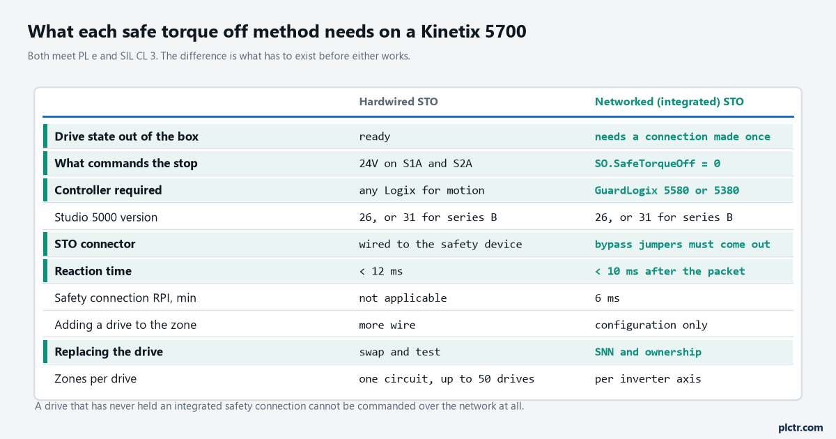
Both rows of ratings are identical. Every other row is a cost that lands on somebody: the panel builder, the programmer, or whoever is on site when the drive fails.
Where the two manuals disagree, and what I would write in the file
This is worth knowing before you quote a controller on a proposal.
The Kinetix 5700 user manual’s integrated safe torque off section says a GuardLogix 5570 or Compact GuardLogix 5370 is required, with Logix Designer version 26 or later. The safe monitor functions safety reference manual, which is the document a safety file cites, puts a GuardLogix 5580 or a Compact GuardLogix 5380 against networked safe torque off in its safety application table, notes version 31 for the drives of series B and later, and adds a footnote that the 5580 and 5380 are backwards compatible with the 5570 and 5370 anyway. The two statements are reconcilable — the older controllers do the job for plain networked STO, the newer generation is what the safety reference manual builds on, and the SS1 and monitoring functions need it — but they are not interchangeable sentences to copy into a specification. I would take the safety reference manual’s table, because it is the one written to be cited.
If the answer matters commercially, confirm the pairing against the current release notes rather than either manual.
Replacing the drive, which is where the choice really bites
A hardwired drive is swapped by an electrician. A networked one is not.
On the network the drive’s identity is its device number plus its safety network number, and the GuardLogix will only push configuration into a replacement under conditions it checks: with a safety task signature present, the replacement needs the correct SNN, correct electronic keying and correct address before the controller will configure it automatically. There is also a Configure Always setting that removes most of that checking, and the warning printed next to it is unusually direct — enable it only where the integrated safety control system is not being relied on to maintain SIL 3 during the replacement and functional test, and never put an out-of-box device on a safety network while it is enabled. One practical trap sits underneath all of it: a replacement drive that has been used somewhere else has to be cleared back to Hardwired STO mode before it goes on the safety network, or its old ownership travels with it. The wider mechanics of that are in safety network number and signature when you replace a safety module, and the same identity rules govern a safety signal between two GuardLogix controllers.
Getting back to hardwired mode is a documented procedure, not a firmware flash.
Inhibit the module, open the Safety category of Module Properties, click Reset Ownership, and the drive reverts. It can also be done from the drive’s own display through the Settings menu, where a Reset Ownership request has to be acknowledged within 30 seconds or the display simply goes home and nothing changes. Either way, the safety connection must be inhibited first; with an active connection the drive answers Reset Failed.
One rule for a dual-axis inverter
Both axes of a 2198-Dxxx-ERS4 share a mode.
You cannot run axis 1 networked and axis 3 hardwired on the same module — the safety application setting belongs to the module, not to the axis. That single line decides more panel layouts than it should, because a machine with one zone that wants a relay and another that wants the safety task has to split them across two inverters rather than across two halves of one. Both axes can still be commanded independently once you are in networked mode, since each has its own SO.Command and SI.Status set, and in hardwired mode axis A and axis B have their own pairs of safety inputs on the plug and can be fed by two different safety devices. The constraint is only the mode itself.
Plan the zones before choosing dual-axis inverters, not after the cabinet layout is fixed.
Next step: read the safety supervisor state on every drive in the machine and write the value next to the tag in the drawing. Anything reading 51 or 8 is in hardwired mode whatever the I/O tree says, and if the panel schedule expected a networked zone there, you have found a machine where the safety function is not the one on the drawing. For the motion side of the same drive, the Kinetix 5700 motion control article covers what the axis is doing when none of this is active.