DCS and the Dual-Channel Family: Discrepancy Time, and the Two Faults With No Timer Behind Them
A DCS instruction reporting Fault Code 16#4002 has not had a discrepancy in the sense anybody means by the word. That code means Channel A went to the safe state and came back to the active state while Channel B stayed active, and the Discrepancy Time operand played no part in it: there is no window, no timer, and raising the setting from 250 ms to 1000 ms changes nothing except the other two codes. The instruction has four fault codes for its two channels, 16#4000 and 16#4001 are a timer expiring, 16#4002 and 16#4003 are a single channel cycling on its own, and knowing which pair you are looking at is the difference between measuring a gate switch and going to find the wire that is making and breaking. Everything below is 1756-RM095O, September 2025, on a GuardLogix 5580 with Guard I/O.
Set the module’s input points to Single. The instructions do the dual-channel work themselves and the manual asks for the points to be configured that way.
Four codes, two of them timed
The Discrepancy Time is the length of time the two channels are allowed to be in an inconsistent state, and what counts as inconsistent depends on the Input Type.
With Input Type set to Equivalent, inconsistent means one channel at 1 and the other at 0, in either order, and the two fault codes tell you which way round it was when the timer ran out: 16#4000 is Channel A active with Channel B safe, 16#4001 is Channel A safe with Channel B active. With Complementary, the active state is Channel A at 1 and Channel B at 0, so inconsistent means both at 0 or both at 1, and the same two codes carry the same which-one-was-where information. Those two are the timed pair, and the valid range for the operand is 5 to 3000 ms. The other two are events, not durations. 16#4002 is Channel A dropping to the safe state and returning while B never left the active state, and 16#4003 is the same thing on Channel B, and the instruction raises them on the return edge regardless of whether the excursion lasted 4 ms or four seconds. A bouncing contact, a crushed cable that makes and breaks as the door swings, a loose ferrule under a terminal screw: all of those land in the second pair, and none of them is improved by a longer window. There is a fifth code, 16#20, which is not about the channels at all; it means the Input Status input went from on to off while the instruction was running, so the I/O connection or whatever logic you used to source that status is what to look at.
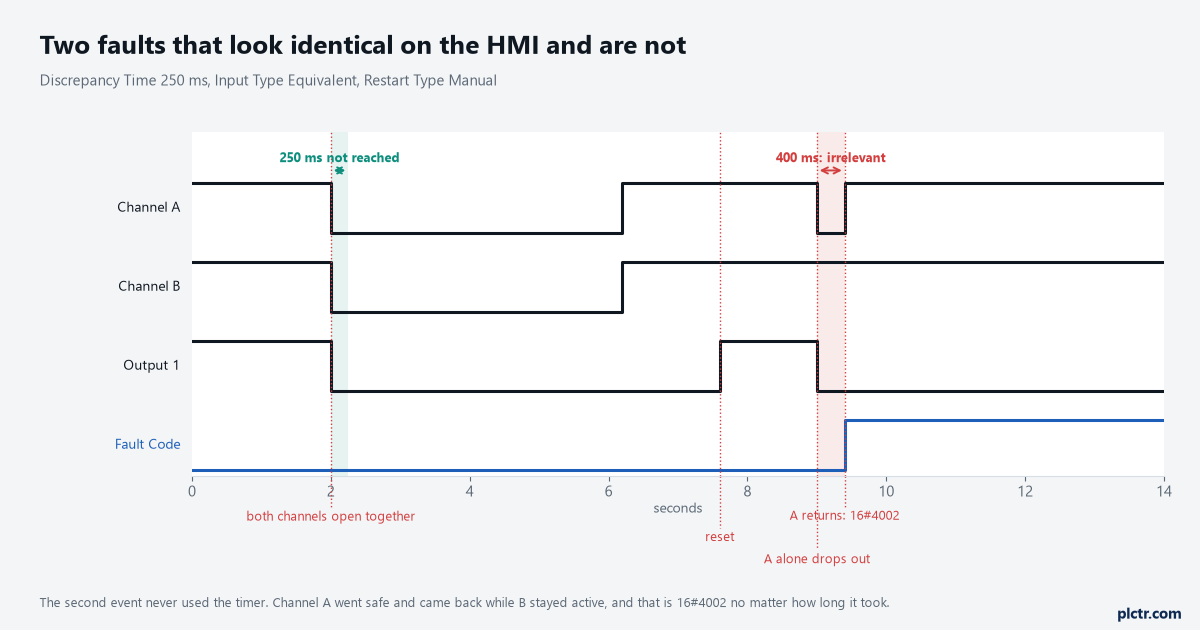
The second event never used the timer. Drawn from the instruction’s own Cycle Inputs and Discrepancy Fault descriptions, and the 400 ms could have been any number at all.
What happens after the fault is cleared is the part people trip over. Reset clears Fault Present and the Fault Code, but Output 1 does not come back with them: after a discrepancy fault the safety inputs have to cycle through the safe state before the output can energise, and only then does a reset do anything. So a gate that faulted has to be opened and closed, properly, with both channels going safe together, before the machine will run. That is not the Cold Start Type behaving oddly. It is the instruction insisting that a device which has just demonstrated it might be broken gets operated once under supervision.
Open the gate, close the gate, then press reset. In that order, every time.
Six instructions, and three different things Discrepancy Time means
DCS, DCST, DCSTL and DCSTM all carry the same operand with the same 5 to 3000 ms range and the same four fault codes. They differ in what they add.
DCST adds a forced functional test: pull the Test Request input from on to off and the instruction de-energises Output 1 and raises Test Command, prompting somebody to operate the device, and the test completes when both channels reach the safe state. DCSTL adds guard locking on top of that, with an Unlock Request input, a Lock Feedback input that must be on before Output 1 can energise at all, a Hazard Stopped input, and a command output that is withheld until the hazard has actually stopped. DCSTM adds muting of the stop device, and it brings one number worth writing on the drawing: its Test Time operand has a range of 5 to 1000 ms, and the manual marks it IMPORTANT that this time cannot exceed 150 ms for type-2 light curtains as specified by EN 61496-1. DCM is the one that is genuinely different in kind. It monitors rather than stops, its documented Safety Function choices are a cam switch or a position limit switch, it has no Restart Type and no Cold Start Type, and its Output 1 simply follows the two channels instead of latching until a reset. Its Discrepancy Time range is 0 to 3000 ms, where 0 disables the check entirely, and it offers an Input Type that none of the stop instructions do: Equivalent – Active Low, where both channels at 0 is the active state. It also has an Instruction Status output that is on whenever Output 1 is valid with no faults and no diagnostics present, which is the cleanest single bit to put on an HMI.
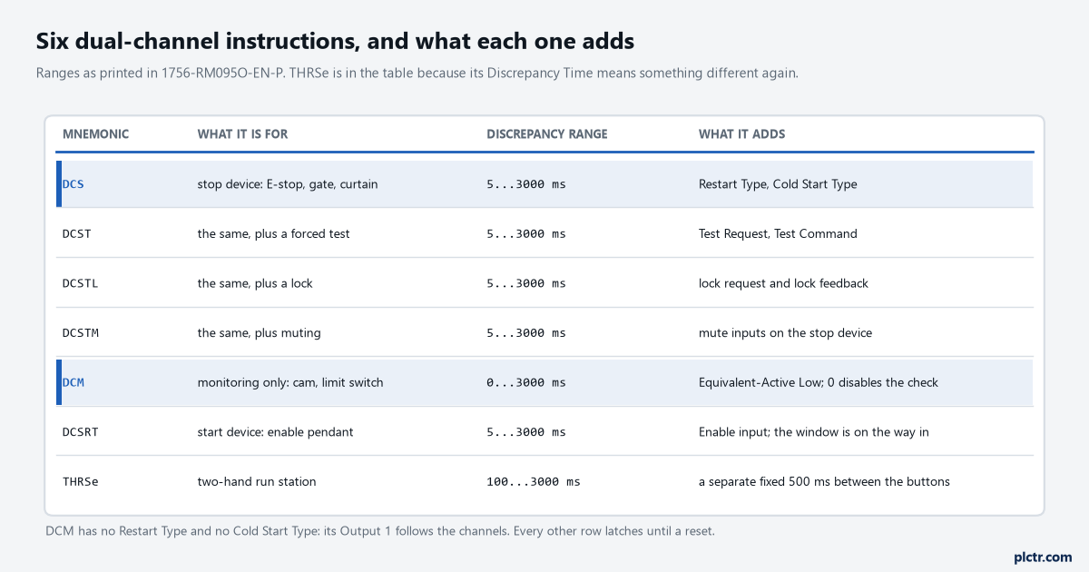
DCM is the row to read twice. Its output follows the channels; every other row latches off until somebody resets it.
One operand name, four different jobs across the family. Read the description, not the label.
DCSRT is the third meaning. It is a start instruction, for a device like an enable pendant, and its Output 1 energises only if the Enable input is on and both channels transition to the active state within the Discrepancy Time, so the window is measured on the way in rather than being a tolerance for disagreement after the fact. And THRSe, the two-hand run station, has a Discrepancy Time with a range of 100 to 3000 ms that applies to the normally-open and normally-closed contacts of one button being inconsistent with each other, which is a fourth idea again, and it sits alongside a completely separate and fixed 500 ms window between the left and right buttons.
The diagnostic codes are not faults
Fault Present is off, Fault Code reads zero, and Output 1 still will not energise. Look at the Diagnostic Code.
Diagnostic 16#4000 means the device has not been functionally tested at startup, and 16#4001 means it has not been tested since a fault occurred. Neither is an error, both are the instruction waiting, and the only thing that clears them is operating the device so both channels go to the safe state. This is what a Manual Cold Start Type produces after every download and after every recovery from an Input Status fault, and it is the single most common “the machine will not start after a download” call on a new GuardLogix. Write it on the commissioning sheet: after a download, cycle every guard and every E-stop once. Diagnostic 16#05 is a different animal, and it means the Reset input is held on, which is a taped button, a jumper, or a mapped HMI bit that nobody ever clears; the instruction is telling you the reset it is being offered is a level and not an edge, and the footnote under the Reset operand is explicit that additional logic may be needed to verify that transition. Diagnostic 16#20 means the Input Status was already off when the instruction started, which is a connection that never came up rather than one that dropped.
A diagnostic will not stop the machine running. It will stop it starting, which looks the same from the office.
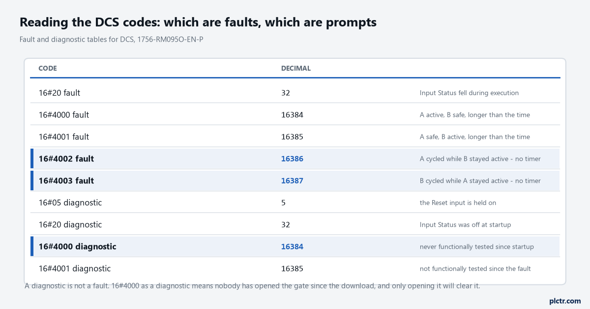
Note 16#20 and 16#4000 appear in both tables meaning different things. Read which output the number came from before you act on it.
What everybody does first
Raises the Discrepancy Time. It is one number in one dialog and it is the obvious lever.
It is the right lever for exactly two of the five codes, and only after the gap has been measured on the device rather than guessed, which is a job of its own and is worked through in the discrepancy time article. For 16#4002 and 16#4003 it does nothing whatsoever, and the time spent proving that is time not spent trending the two channels at the safety task period and watching which one glitches. For 16#20 it does nothing either, and the answer there is the I/O connection. The second move people make is to set the module’s input points to Equivalent so the module does the pairing, which masks the instruction’s own fault from the controller and leaves you with a module status bit instead of a code that names the channel; the same trap is described from the migration side in the 440R article. Leave the points single. And remember that the instruction only sees its inputs once per safety task execution, so a 50 ms discrepancy time on a 20 ms task period is a window two or three samples wide, and any setting that approaches the task period is not really a setting at all.
Two codes, two different failures. One is a device that is slow, the other is a device that is intermittent.
Next step
Read the Fault Code and the Diagnostic Code from the instruction’s backing tag before anything else, and write both numbers down. If it is 16#4000 or 16#4001, trend Channel A and Channel B at the task period across ten operations of the device, take the worst gap, and set the Discrepancy Time above it with margin that reflects how the device ages. If it is 16#4002 or 16#4003, stop looking at the setting and start looking at the channel the code names: the wire, the ferrule, the contact block, the cable where it enters the duct. If it is a diagnostic rather than a fault, the machine is waiting for somebody to operate the device, not for somebody to fix it. The next article covers the instructions where a single timer is not enough, because the safety function depends on four sensors arriving in the right order.