The Safety Task on a GuardLogix: What Runs In It, What Cannot, and How to Pick the Period
The Safety Task Properties dialog on a GuardLogix 5580 takes a period between 2 and 500 ms and a watchdog between 2 and 500 ms, and the safety reference manual is explicit that the watchdog has to be less than or equal to the period. Pick that pair badly and nothing complains at download. The controller faults the first time the safety logic runs longer than the watchdog, the fault is nonrecoverable, and every safety output goes to its safe state and stays there. So the short answer to “what period should I use” is: the largest one your reaction time calculation will accept, with a watchdog that has measured headroom over the worst safety task scan you have actually seen, and not a millisecond smaller. Everything below is 1756-RM012J, the September 2025 safety reference for the 5580 and Compact 5380 families, plus the instruction set reference where the instructions themselves set a limit.
There is one safety task per controller. You cannot add a second, and you cannot delete the one you have.
What the task actually is
It is a periodic task with four differences that matter, and the fourth one catches people who have written standard Logix for years.
A periodic task in a Logix controller is triggered at a repetitive interval, interrupts the continuous task, and leaves its outputs at their last value until it runs again, all of which is ordinary Logix scan behaviour. The safety task does all of that. Then: safety input tags and safety-consumed tags are refreshed only at the start of an execution, so a 5 ms RPI into a 20 ms task gives you data that is up to 20 ms old and no fresher, and packets that arrive mid-execution are buffered for next time. Safety output tags are written to the modules at the end of the scan, and produced safety tags go out to consuming controllers at the same moment. Standard tags that you have mapped are copied in at the start, and a change your safety logic makes to the copy never travels back to the standard tag. And time is frozen at the start of the safety task execution, which means a TON or a TOF inside the safety task does not advance its accumulator during the scan at all. It keeps accurate time from one execution to the next, but within one pass through the logic the clock does not move. The manual flags this as differing from standard Logix task execution, and it is the one that produces a puzzled engineer at a laptop: a safety timer preset of 8 ms on a 20 ms task period is a timer that can only ever be 0 or 20.
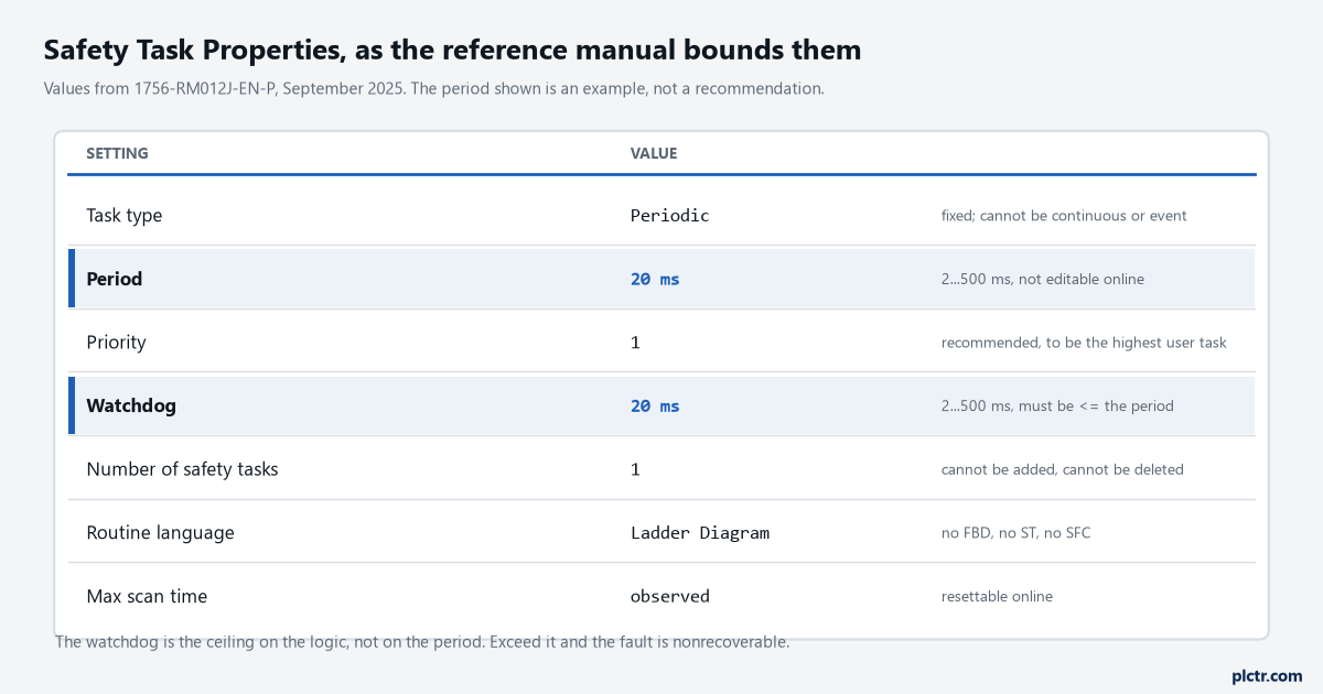
The period cannot be changed online at all. The watchdog can, unless the controller is safety-locked or a safety signature exists, which on a commissioned machine it will be.
Priority is the one parameter that is not a safety concern. The manual says so directly: the watchdog is what catches a higher-priority task stealing time, so priority only affects how much the execution time wanders. The recommendation is 1, to make the safety task the highest priority user task, and that is worth taking because a tighter spread in execution time lets you set a tighter watchdog, and the watchdog is in the reaction time.
The motion task still wins. It is always higher priority than any user task, safety included.
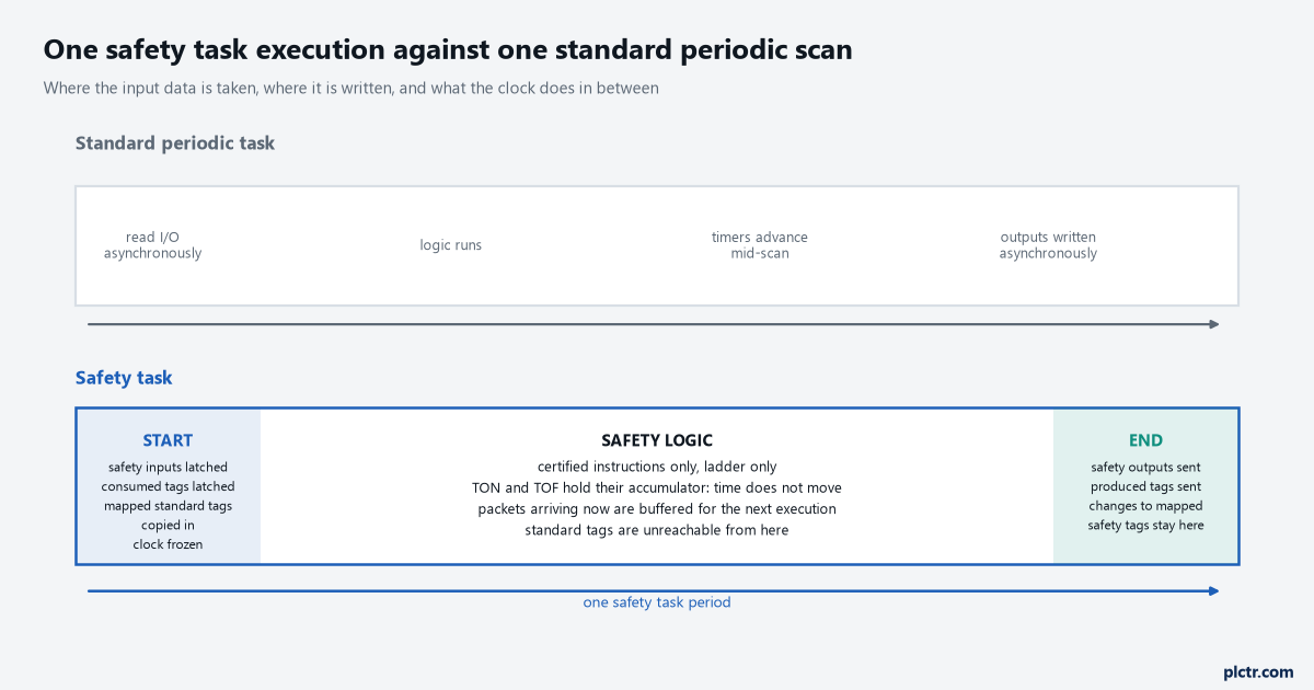
The two shaded ends are where all the I/O happens. Everything in between sees one frozen snapshot, which is what makes the dual-channel instructions able to measure a discrepancy in whole task periods.
What will not go in it
Ladder only. Not function block, not Structured Text, not sequential function chart.
Safety routines live only inside safety programs, safety programs are scheduled only in the safety task, and a safety program contains no standard routines and no standard tags. A safety routine cannot read or write a standard tag at all, which is what safety tag mapping exists to work around, and a JSR from inside the safety task to a standard routine is refused. The instruction set is the safety application instructions plus a certified subset of the standard ladder set, and the subset is generous: TON, TOF, RTO, CTU, CTD and RES are all there, so are ONS, JSR, SBR, RET, JMP, LBL, MCR and AFI, so are COP, FAL, FSC, FFL and the file instructions, and so is most of the arithmetic including CPT, SQRT and the trigonometric set. Rockwell attaches a caveat to some of them worth reading before you lean on one: they have done no independent mathematical analysis of the numerical algorithms in the advanced math, square root and trigonometric instructions, and if you need a specific accuracy you have to test the instruction across your own input domain. COP carries its own condition, that the length must be a constant and the source and destination lengths must match. GSV and SSV are available but the safety task cannot perform them on standard attributes, and no SSV in either task can set the major-fault-on-error bit in the mode attribute of a safety I/O device. There is a watermark on the routine so you can tell at a glance which one you are in.
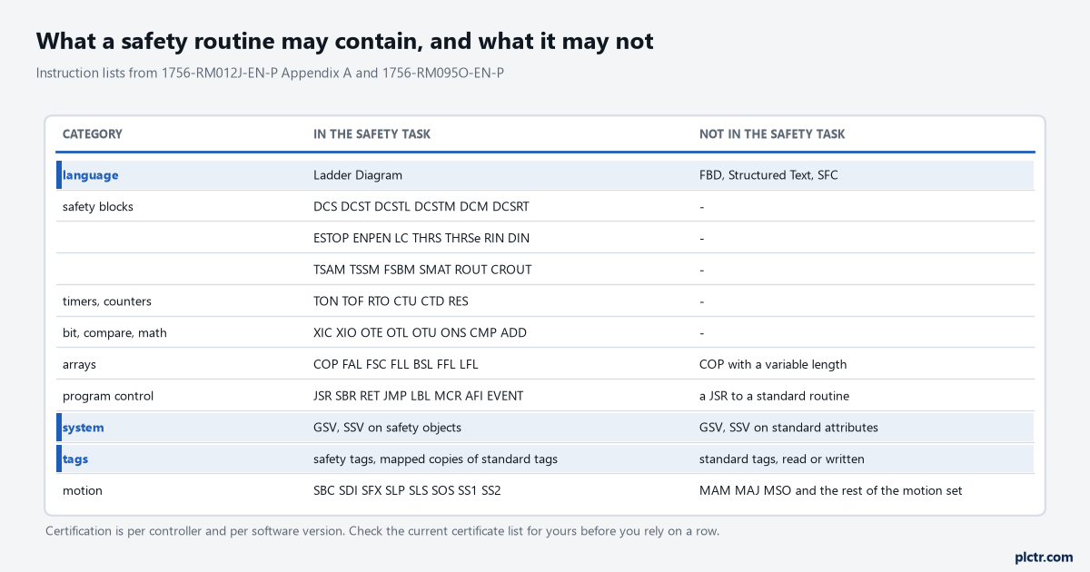
The motion row is the one people argue about. The drive safety instructions run in the safety task; MAM, MAJ and MSO do not, and an axis is commanded from standard logic while its safe speed is watched from here.
Add-On Instructions can be safety Add-On Instructions, built from certified instructions, and they carry a safety instruction signature of their own that is checked on download. If you go that way, initialise your critical AOI tag values in the AOI’s prescan logic, because the manual is blunt that you must.
Picking the period from the reaction time, not from the feel of it
The period is an input to two separate numbers, and only one of them is obvious.
The obvious one is the controller’s own contribution: safety task reaction time equals the safety task period plus the safety task watchdog, multiplied by 1.01 for clock drift. A 20 ms period with a 20 ms watchdog contributes 40.4 ms. The less obvious one is the output connection reaction time limit, because for safety output connections the RPI is fixed at the safety task period, and the limit works out as the period multiplied by the sum of the timeout multiplier and the network delay multiplier less one. At the defaults, that is three times the period: 60 ms on a 20 ms task, 30 ms on a 10 ms task. The input side does not move with the period at all, because the input connection reaction time limit is the input RPI times the sum of those two multipliers, and RM012J puts a specific warning on it: the default values produce an input connection reaction time limit of 40 ms, and if you leave the defaults alone that 40 ms is the figure that has to go into the calculation. There is a second warning next to it that matters in practice on a busy network, that for applications with safety I/O the default limits can cause connection loss and sometimes have to be increased, at which point the new, larger number is the one the calculation uses. Add the sensor and the actuator at each end and you have the system reaction time, worked through end to end for one guard in the 440R migration article, and that is the number the risk assessment measures the guarding distance against, not the period on its own.
Halving the period does not halve the chain. It moves two of the five terms.
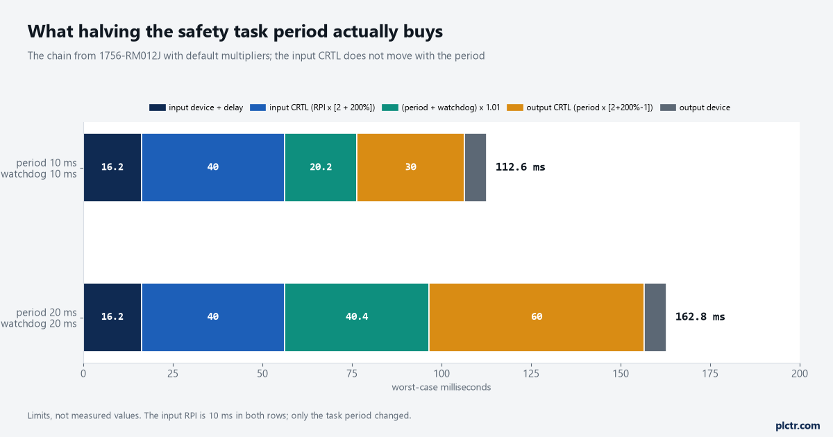
The input device and input CRTL figures here are an example set, not values from your system. Read your own from the module properties dialog and the device datasheet before you put them in a calculation.
Two instructions set their own ceiling on the period, and both are easy to miss. THRSe requires the two buttons of a two-hand run station to be pressed within 500 ms of each other, and the instruction set reference states plainly that for this to be detected properly the safety task period cannot exceed 40 ms and the input device RPI cannot exceed 20 ms. The Light Curtain instruction’s software filter has a related constraint from the other direction: a filter time set above the safety task period is what makes the input have to read low for several consecutive scans, and the manual works the arithmetic at a 5 ms task period to show a 10 ms filter needing three low scans and a 15 ms filter needing four. Neither of these appears anywhere near the task properties dialog. You find them when the two-hand station will not fire and somebody has set the period to 50 ms to make room for a large routine.
The lower limit nobody writes on the drawing
The instructions in your safety task, and in any higher-priority task, set the floor under both the period and the watchdog. There is no table for it.
RM012J says as much in as many words and then leaves you to measure. Large amounts of mapped safety tags or large amounts of produced and consumed safety tag data cause the safety task scan time to fluctuate, so the first thing to do after the logic is written is to watch the maximum scan time on the Safety tab while the machine runs its worst cycle, and to reset it and watch again. There is a trap while you are still commissioning: before the controller is safety-locked and while no safety signature exists, the controller prevents simultaneous write access to safety memory from the safety task and from communications, which means the safety task can be held off while a communication update finishes, the hold-off scales with tag size, and the manual’s advice is to raise the watchdog to cover it. Once the controller is safety-locked or a signature exists, that scenario cannot happen. So a watchdog tuned during commissioning is tuned against the pessimistic case, which is the right way round. A watchdog tuned after the signature exists is tuned against the easy case.
One more powerup oddity to know about. If the controller is configured for SIL 2 and the slot to its right is empty or holds a non-safety module, the safety task execution can be delayed on powerup by five seconds or more.
What everyone checks first, and it is almost never it
The logic. Somebody opens the safety routines looking for the expensive rung.
A safety task that overruns its watchdog usually has not grown a slow instruction; it has grown mapped tags, or produced and consumed tag data, or it is being interrupted by something with a higher priority that also grew. Look at the count of mapping pairs first, because the copy happens every execution and every pair adds to it, and mapping one structure instead of thirty booleans is the fix that costs nothing. Then look at what else runs at priority 1 or above and what the motion group is doing, because the motion task outranks the safety task by design. Only then read the rungs. And if the fault arrived the same afternoon somebody went online, check whether the safety signature has been deleted, because the communication hold-off above is real and it comes back the moment the signature goes.
Next step
Write down three numbers before you touch the period field: the safety task reaction time you need, worked backwards from the guarding distance in your risk assessment; the input connection reaction time limit your modules are actually configured for, read off the Safety view of each module’s properties rather than assumed to be the 40 ms default; and the worst safety task scan time you have measured with the machine doing its heaviest cycle. The period follows from the first two, and the watchdog follows from the third with margin. Then check the instruction list above against what you intended to write, because finding out that a routine has to be ladder is cheaper before it is written than after. The next article in this set takes the first safety routine and the one thing every project needs on day one, which is getting a standard tag into it legally.