Point Operation Type reads Dual-channel Equivalent, Discrepancy Time reads 500, and nothing on the 1791ES-IB8XOBV4 Input Configuration tab tells you whether 500 ms is right for the gate switch you just landed on I0 and I1. The value is not a tuning knob for nuisance trips. It is the width of the window in which the two channels are allowed to disagree, and anything outside that window the module is required to treat as a broken safety function.
Short answer: it is the longest stagger the device produces when a person operates it normally, plus a margin, and nothing more. Rockwell’s own instruction in 1791ES-UM001H is blunt – “Do not set the discrepancy time longer than necessary” – and the module will take 0…65,530 ms in 10 ms steps, a range wide enough to let you set something ridiculous. The Discrepancy Time operand in the DCS instruction takes 5…3000 ms, and on a GuardLogix that is the setting most applications should be using. The rest of this is why, and which of those two the controller is really looking at.
Examples are a 1791ES-IB8XOBV4 on EtherNet/IP with a GuardLogix 5580, Studio 5000 Logix Designer, and DCS in the safety task.
What the second channel is actually there for
One channel tells you the guard is open. Two tell you the guard is open and that the thing telling you has not quietly stopped working.
The failures worth naming are dull ones. A contact block welds shut. An actuator wears and one block stops opening at full travel. A wire chafes through where the cable enters the duct. Somebody puts a spare key in the switch and tapes it there because the door has to stand open for a changeover. With one channel every one of those leaves you a signal that says “closed” forever and no way to know; with two, the module gets two independent statements about the same door and a single failure shows up as a disagreement instead of as silence.
That is also why the two channels get separate test sources.
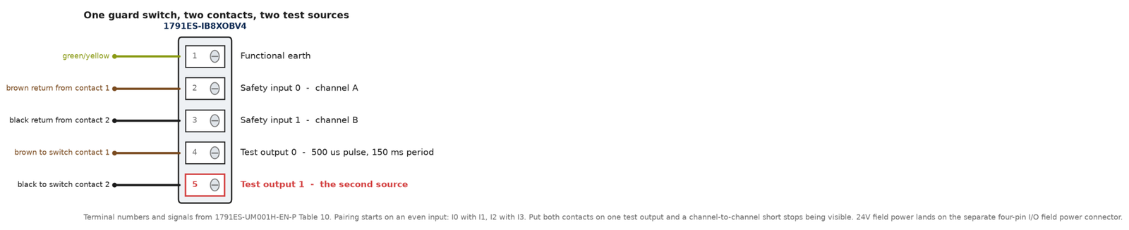
Rockwell’s wiring table in 1791ES-UM001H connects an E-stop or door monitor as contact one between T0 and I0 and contact two between T1 and I1, so a short between the two field wires puts one channel’s pulse train onto the other and the module sees it. Those pulses are small and fast – 500 µs wide, repeating every 150 ms – and they are the reason a cross-fault does not look like a healthy gate.
Wire both channels off the same test output and that detection is gone.
The terminal-by-terminal version of that wiring is in dual-channel E-stop wiring on GuardLogix.
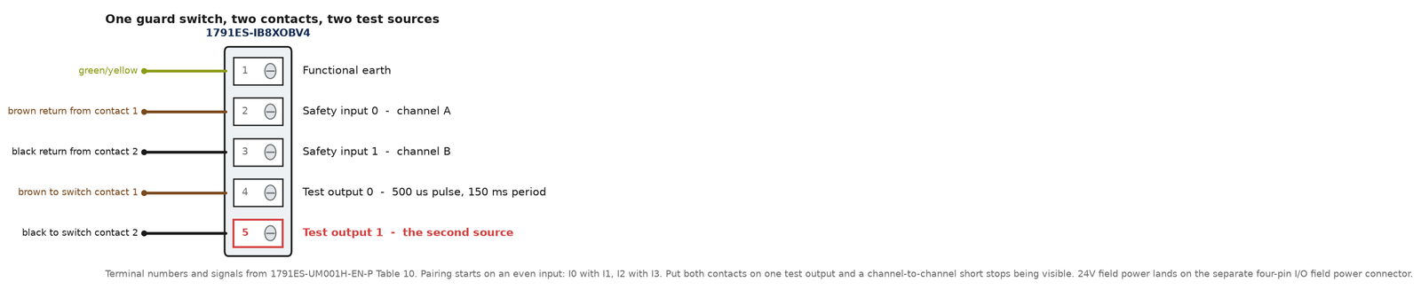
Rockwell’s table also puts a number on what that wiring buys. A single-channel safety device pulse-tested from one test output is listed at Safety Category 2 with a maximum Performance Level d; an E-stop or door monitor on two inputs with two test outputs is listed at Category 4 with maximum Performance Level e. Those are Rockwell’s entries for its own module, and they are the vendor’s summary: what Category 4 and PL e actually require is defined in ISO 13849-1, which is not reproduced here. A machine does not inherit a rating from a module either. The rating belongs to the whole safety function, sensor through logic to contactor.
The second channel is structure. The discrepancy time is what makes that structure testable.
What the discrepancy time window counts as a disagreement
Two things, depending on how you set Point Operation Type.
In Equivalent mode both inputs of a pair are normally in the same state, and a discrepancy begins the moment one transitions before the other. In Complementary mode they are normally opposite, and it begins the same way. The pairing is not free-form: dual-channel operates on two consecutive inputs starting at an even number, so I0 with I1, I2 with I3, and so on up the module. Land the two contacts on I1 and I2 and there is no pair to configure, which is a five-minute mistake to make and an hour to find because everything else about the wiring looks right.
While that timer is running, nothing is wrong yet. That is the entire point of the setting.
Two places to set it, and only one of them the instruction sees
Here is the part that catches people who have been using Guard I/O for years.
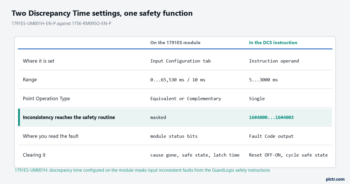
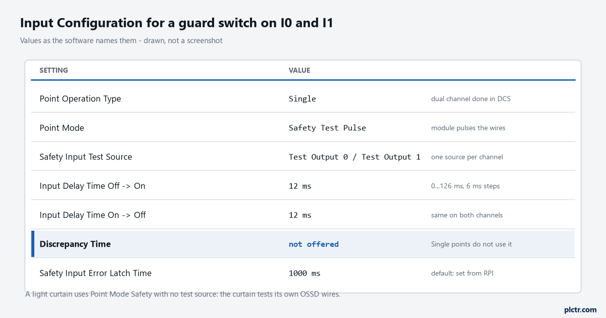
The Discrepancy Time on the Input Configuration tab belongs to the module. The Discrepancy Time operand in the DCS instruction belongs to the safety task. They are separate settings with separate ranges, and 1791ES-UM001H carries a one-line footnote under its input parameter table explaining why you should not have both: if you configure discrepancy time on safety I/O modules, it masks input inconsistent faults from the GuardLogix safety instructions. The module resolves the disagreement itself, sends both channels up to the controller as a matched pair, and the DCS instruction never sees the inconsistency it exists to catch. The status bits still carry it, and GuardLogix can read module status to get the fault information, but nothing in your safety routine is looking for it. Rockwell says the same thing from the instruction’s side, in a bolded IMPORTANT at the head of the DCS operand table in 1756-RM095O: make sure that your safety input points are configured as single, not Equivalent or Complementary, because these instructions provide all dual-channel functionality necessary for the safety function.
So the default answer on a GuardLogix is points Single, evaluation in DCS, discrepancy time set there.
A third variant is worth knowing because it shows how much freedom this setting really has. On a Guardmaster 440C-CR30 configurable safety relay the discrepancy time runs 0…3 seconds in 50 ms increments, the default value is 2 – which 440C-UM001I spells out as 2 × 50 = 100 ms – and the same manual says flatly that if the discrepancy time is set to 0, the discrepancy test does not occur. Read that again if you have been assuming this check is welded into the hardware. It is a number in a configuration file, it has a legal value that turns it off, and somebody with a laptop and the password can set it. On a machine you did not commission, “it’s dual channel” is a statement about the wiring and tells you nothing about whether anything is being compared.
Go and look at the value before you trust it.
Picking the number from the device, not from a default
Start by asking what produces the stagger, because that is the only thing this number is allowed to cover.
A mechanically linked guard switch has two contact blocks driven by one actuator and they do not change state at the same point of travel. On a heavy sliding gate that somebody pushes closed by hand, the gap between contact one changing and contact two changing is a function of how fast that person is moving, and it is not the same at 06:00 as it is twenty minutes before the end of a shift. 440C-UM001I names the case directly in its list of what the channel test is looking for: slow-moving doors or gates that use non-snap-acting contacts. That is your lower bound. The value has to be longer than the slowest honest actuation or you will fault the machine on a perfectly good door, and the operator will learn to slam it, which is its own problem.
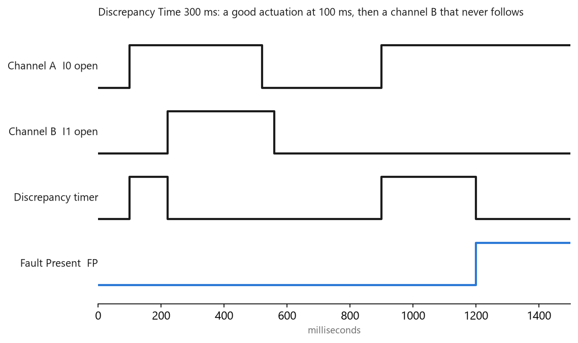
The upper bound is the one people ignore. 1791ES-UM001H says the purpose of the discrepancy time is to allow for normal differences between contact switching when demands are placed on the inputs, that for the testing to operate correctly only one demand is expected during the discrepancy time, and that if the time is set too high and multiple demands occur inside it, both safety input channels will fault. So a five-second discrepancy time on a gate an operator cycles every four seconds is not a more forgiving machine. It is a machine that faults for a reason nobody on site will ever connect to the setting.
Both bounds come from the mechanism. Neither comes from the module.
The working method is dull and it takes half an hour. Put both channel bits in a trend at the safety task period, get somebody to open and close the guard the way it actually gets opened and closed – slowly, one-handed, from the far corner, with the gate slightly out of square because it has been kicked – take the worst gap you see across a few dozen operations, and set the next 10 ms step above it with margin on top. Two things add to that gap before the module starts its timer, and they are in the same dialog: Input Delay Time Off→On and On→Off are per-channel filters running 0…126 ms in 6 ms steps, so a pair filtered 24 ms on one channel and 0 ms on the other has 24 ms of discrepancy built into the configuration before anybody touches the door.
Set them the same on both channels of a pair unless you have a reason not to, and write the reason down when you do.
A value measured on one door is a value for that door. The infeed gate and the discharge gate are two different mechanisms with two different answers, and copying the number across because both of them are gates is how a line ends up nuisance-tripping on one side only.
Why a light curtain wants a different number
Because there is no mechanism to allow for.
Rockwell’s wiring table connects a light curtain by landing OSSD1 on I0, OSSD2 on I1 and tying the 24V commons, with no module test output involved, because the curtain tests its own output wires. The point mode for that input is Safety rather than Safety Test Pulse, and 1791ES-UM001H describes Safety as the setting for a device that performs its own pulse tests on the wires, giving a light curtain as the example. Both OSSDs are switched by the same electronics, in the same device, on the same beam interruption. The mechanical stagger you were allowing for on a guard switch does not exist, so the window that made sense for the gate is many times wider than anything the curtain will ever produce.
That argues for a short discrepancy time on a curtain and a longer one on a hand-pushed gate, which is the reverse of how they usually get configured: one number, typed once, copied to every dual-channel pair in the project because the first one worked. If you need the actual switching difference between OSSD1 and OSSD2 for a specific curtain, that figure is in the curtain’s own manual – it is not in the Guard I/O manual, and I am not going to invent one.
What expiry does, and what it takes to get back
On the module, the fault is not subtle. If the second transition does not happen before the discrepancy time elapses, the channels fault: safety input data and individual safety input status turn off for both, and on a complementary pair the fault state is the even-numbered input off and the odd-numbered input on with both status bits low. You can read the cause over explicit messaging – Get Attribute Single, class 3D hex, attribute 6E hex, on the instance for that input – where 04 is a discrepancy error and 05 is error in the other dual channel input, which is what the partner channel reports. That second code is how you tell which of the pair actually failed.
Recovery is a sequence, not a button. 1791ES-UM001H gives three steps: remove the cause of the error, put the safety input or inputs into the safety state, and then the safety input status turns on and the red I/O indicator goes out once the input error latch time has elapsed. That latch time is its own parameter – 0…65,530 ms in 10 ms steps, default 1000 ms – and it is there so a fault that existed for three milliseconds is still present long enough for the controller to read it across the RPI, which is set the way any EtherNet/IP connection sets its RPI. The manual is explicit that the amount of time to latch must be based on the RPI, the safety task watchdog and the rest of the application.
Wind it down because the indication is annoying and you will start losing the faults you needed to see.
In the instruction the picture is more useful, because the fault code says which channel was which.
| Fault code | What it means |
|---|---|
| 16#4000 (16384) | Inconsistent for longer than the Discrepancy Time; at the moment of the fault Channel A was active and Channel B was safe |
| 16#4001 (16385) | The same, with Channel A safe and Channel B active |
| 16#4002 (16386) | Channel A went to the safe state and back to active while Channel B stayed active |
| 16#4003 (16387) | Channel B went to the safe state and back to active while Channel A stayed active |
The last two are not discrepancy faults at all. They say one channel bounced – a loose crimp, a chattering contact, an actuator that rattles at the end of travel – while the other never moved, and knowing that distinction saves an afternoon of staring at the wrong door. Clearing any of them takes an OFF-to-ON transition of the Reset input, which resets the Fault Present output and the Fault Code. Getting Output 1 back on afterwards takes more than that: 1756-RM095O is specific that after a discrepancy fault the safety inputs must cycle through the safe state before a reset will energise the output. Open the guard fully, close it, then press reset, in that order. And when the fault codes are clear and the output still will not come on, read the Diagnostic Code – 16#05 means the Reset input is being held on, which in practice is a jumper, a stuck pushbutton, or a test bit somebody latched in Program mode and forgot.
What everybody checks first
The wiring.
It is almost never the wiring, on a machine that ran for a year and started faulting last month. A cross-fault between the two channels gets caught by the test outputs and reports as an external test signal error, cause code 02, not as a discrepancy. A broken wire on one channel leaves that channel permanently in the safe state, which gives you a discrepancy on the first actuation and then a consistent fault that does not come and go. A discrepancy that appears intermittently, on one door, more often on late shift, is a mechanism every time: worn actuator, sagging gate, a door that is now closed with a shoulder because the handle broke in March. The cable in the duct is the thing you can test from a chair, which is why it gets tested first, and it is the least likely answer on the list.
Go and watch the door being used before you pull anything apart.
Next
Decide which of the two settings your project is actually using before you type a value into either, because a module configured Equivalent with a discrepancy time is quietly answering the question your DCS instruction thinks it is asking. Then let the mechanism give you the number: trend both channels, open the guard fifty times, take the worst gap. When it is set, write it on the drawing next to the switch catalogue number, because nothing on the panel will tell the next person what it is or why. For the reset and restart behaviour that has to sit behind all of this, safety instructions and their reset parameters is the next piece, and risk assessment through to a PL d architecture is where the requirement for two channels came from in the first place. For a machine whose own product standard sets the guard expectation, the molding case is in injection molding cycle, barrel zones and guard interlocks.