A functional safety PLC project is not “buy a GuardLogix and write the E-stop rung”. The order of work is fixed by the standards: assess the risk, define the safety function, set a required performance level, then build an architecture that can prove it. Get that order wrong and you end up with a tidy dual-channel circuit nobody can justify on paper. What follows is the vocabulary and the arithmetic, with a worked PLr determination and a PFHd budget you can copy.
Wiring and instruction settings for one specific door and E-stop function are in PLC safety interlock systems. Treat this as the layer above that.
The standards you will actually be asked about
| Standard | Sector | Metric | Where it bites |
|---|---|---|---|
| IEC 61508 | Generic parent standard | SIL 1 to 4, PFD and PFH | Component makers design to it. You quote their numbers. |
| ISO 13849-1 | Machinery | PL a to e, Category, PFHd | The route almost every machine builder takes |
| IEC 62061 | Machinery, electrical | SIL CL 1 to 3, PFHd | Common where a process customer thinks in SIL |
| IEC 61511 | Process industries | SIL 1 to 3, SIF and SIS | Burner management, tank overfill, emergency shutdown |
| ISO 12100 | Machinery | No metric | The risk assessment method the others assume you did |
ISO 13849-1 and IEC 62061 cover the same ground for machinery. Pick one per machine and stay inside it. Mixing a PL from one subsystem with a SIL CL from another in the same calculation is where audits go badly. The rough equivalence is PLb and PLc near SIL 1, PLd near SIL 2, PLe near SIL 3.
Run the risk assessment before you pick hardware
- Set the limits of the machine to ISO 12100: what it does, who touches it, in which modes, over what life. Jam clearing and maintenance count, and that is where most injuries happen.
- List the hazards per operating mode. Be specific. “Crushing between the carriage and the frame while clearing film” is a hazard. “Moving parts” is not.
- Estimate the risk for each one with no protective measure in place.
- Try to design the hazard out, or guard it mechanically. A fixed guard needs no PL, no diagnostics and no proof test.
- Whatever is left becomes a safety function in the control system.
Write each remaining function into a safety requirements specification. One page per function is enough, and it is the document your verification gets checked against later.
SRS-04  Guard door, palletiser wrap station

  Safety function   Opening the door stops carriage and turntable motion
  Trigger           Door open, either channel
  Safe state        Motion power removed, STO on both drives, brake applied
  Response time     250 ms maximum, stopping distance measured 190 mm at speed
  Restart           Manual reset, edge on release, door closed first
  Mode coverage     All modes except setup mode 3, reduced speed with enabling device
  Required PL       PLd, category 3
  Proof test        Functional test at commissioning and every 12 months
  Replacement       Contactors K41 and K42 at T10d, see maintenance plan
Determine the PLr with the risk graph
ISO 13849-1 Annex A gives a risk graph with three parameters. Severity S1 is reversible injury, S2 is irreversible injury or death. Frequency F1 is seldom or short exposure, F2 is frequent or continuous. Avoidance P1 means the hazard can be avoided under certain conditions, P2 means it scarcely can.
Worked example, the palletiser door from the specification above:
- Severity. The carriage weighs 140 kg and travels across the working position. A hand caught there is broken, not bruised. S2.
- Frequency. Operators clear film jams four to six times a shift and open that door every time. F2.
- Avoidance. The carriage runs at 0.3 m/s, it is visible from the door, and there is somewhere to step back to. P1.
S2, F2, P1 lands on PLr d. Change the last answer to P2 and it becomes PLr e, which means category 4 and a different budget. That is why the avoidance parameter gets argued about in every design review. Record the reasoning, not just the letter, because the first person to ask why P1 was chosen will be an inspector.
Pick an architecture that can reach the PL
Category is architecture, and it sets the ceiling.
| Category | Behaviour on a single fault | Typical build |
|---|---|---|
| B | Function lost | Standard relay or standard PLC logic |
| 1 | Function lost, faults less likely | Well tried components, oversized contactors |
| 2 | Function lost between tests | Single channel, tested periodically by the machine control |
| 3 | Function kept, most faults detected | Dual channel, cross monitored |
| 4 | Function kept, faults detected before the next demand | Dual channel, high diagnostic coverage |
For PLd the usual answer is category 3, and the result then depends on two more numbers.
MTTFd is the mean time to dangerous failure of one channel, capped at 100 years in the calculation. Low is 3 to 10 years, medium 10 to 30, high 30 to 100. For a contactor you work it out from B10d and the real duty cycle:
nop   = operations per year
      = 30 per day x 240 working days              = 7 200
T10d  = B10d / nop        = 1 300 000 / 7 200      = 180 years
MTTFd = B10d / (0.1 x nop) = 1 300 000 / 720       = 1 805 years, capped at 100
T10d matters more than people expect. It is the point at which the component has to be replaced, and on a machine cycling every four seconds instead of once a shift it arrives inside a year.
DCavg is diagnostic coverage: none below 60 percent, low 60 to 90, medium 90 to 99, high 99 and above. Pulse tested inputs, cross monitoring between channels and contactor feedback are what buy it.
Category 3 with DCavg low and MTTFd high gives PLd. So does category 3 with DCavg medium and MTTFd medium. Category 3 with DCavg low and MTTFd medium only reaches PLc, which is the trap in this table: the architecture looks right and the answer comes out one letter short.
CCF, common cause failure, is a 65 point checklist in Annex F: separation of channels, diversity, protection against overvoltage and temperature, competence, environmental testing. Score 65 or the category 3 claim drops to category B.
Build the PFHd budget
PFHd is the probability of dangerous failure per hour, and the subsystems add up. The bands are fixed:
| PL | PFHd per hour |
|---|---|
| a | 1e-5 up to 1e-4 |
| b | 3e-6 up to 1e-5 |
| c | 1e-6 up to 3e-6 |
| d | 1e-7 up to 1e-6 |
| e | 1e-8 up to 1e-7 |
A realistic PLd door function:
| Subsystem | Devices | PFHd |
|---|---|---|
| Input | Two coded magnetic switches on pulse tested points | 1.4e-8 |
| Logic | GuardLogix 5580 with 1734-IB8S and 1734-OB8S | around 2e-9 |
| Output | Two 100S-C contactors, mirror contacts fed back | 2.5e-8 |
| Total | about 4.1e-8 |
That total sits inside the PLe band. The function is still only PLd, because PFHd is rarely the binding constraint. Category, DCavg and CCF are. Engineers new to this spend a week hunting for parts with lower PFHd and never notice the claim failed on a CCF question about cable routing. Use the vendor figure where one is published, and calculate from B10d where there is not. Contactors, pneumatic valves and mechanical switches are B10d parts.
Get the response time right
The PL tells you how reliable the function is. It says nothing about how fast. Stopping distance comes from response time, and you add up every link in the chain.
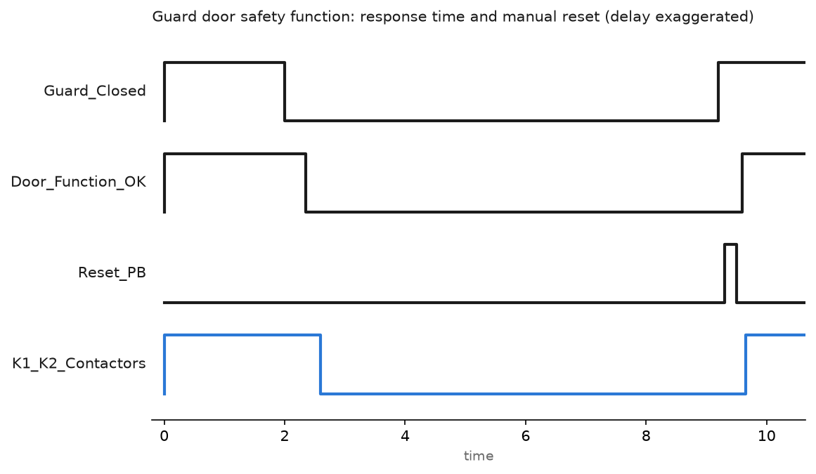
The delay in the chart is drawn wide so you can see it. On a GuardLogix chain the terms are the input filter, the safety connection RPI, the safety task period, the output connection RPI and the contactor drop-out time. A 20 ms safety task with 10 ms RPIs and a 15 ms contactor gets you to roughly 100 ms of control system delay before any mechanical run-down. Rockwell publishes a reaction time worksheet per controller family, but measure the real stopping performance with a stopping time analyser and place the guard using the measured number. Background on how the safety task shares the controller with standard logic is in PLC scan time and cycle time.
GuardLogix or S7-1500F
| Point | GuardLogix 5580 | SIMATIC S7-1500F |
|---|---|---|
| Capability | Up to SIL 3 and PLe | Up to SIL 3 and PLe |
| Software | Studio 5000 with the safety option | TIA Portal Safety Advanced |
| Safety logic | Ladder only, in the Safety Task | LAD or FBD, in an F-runtime group |
| Instruction set | DCS, DCSTL, CROUT, SFX and the rest of the safety set | ESTOP1, SFDOOR, FDBACK, MUTING from the F library |
| Distributed safety | CIP Safety over EtherNet/IP | PROFIsafe over PROFINET |
| Change control | Safety signature, generated on verify | Collective F-signature plus per block signatures |
| Mixed use | Safety and standard tasks in one controller | Safety and standard in one CPU |
Both give you a signature that changes the moment anyone edits the safety program. Print it with the date and keep it in the machine file.
SISTEMA, and what it cannot do for you
SISTEMA is free software from the IFA in Germany. You build the safety function as subsystems, enter category, MTTFd, DCavg and the CCF checklist, and it returns the PL with the PFHd. Most safety component makers publish SISTEMA libraries, so you import an .slb file instead of retyping data sheets.
What comes out is a report. It is not a certificate and it makes nobody compliant. Conformity is declared by the machine builder on the strength of the risk assessment, the calculation, the validation to ISO 13849-2 and the technical file. No safety function is validated from a software report, or from an article, this one included. In Europe the Machinery Regulation 2023/1230 replaces the old Machinery Directive from 20 January 2027, so check which one your declaration cites before it leaves the building.
Validation to ISO 13849-2 means testing against the fault lists. Short one channel and prove the function still works and the fault is annunciated. Hold a contactor closed and prove the feedback loop catches it. Write down what you did, what happened, the date and who watched.
Field notes
The category 3 that was really category B. A palletising cell passed its works test with dual channel everything. During the CCF review it turned out both channels of every door switch ran in the same unprotected multicore, clipped along the frame where pallet trucks hit it twice a week. The separation question in Annex F dropped the score under 65. The fix was a second route for channel B and nothing else. Same components, same logic, two performance levels of difference on paper.
The PLr that moved after a product change. A wrapping station was assessed at PLc when the line ran one pallet every ninety seconds. Two years later a new SKU doubled the rate and operators were opening that door twenty times a shift. Nobody reopened the risk assessment. The exposure parameter had gone from F1 to F2 and the target was PLd. A risk assessment is tied to how the machine is used, so a production change is a reason to look at it again.
The proof test that never happened. A pneumatic dump valve on a press had a T10d of eight years. Fourteen years in, nobody had replaced it, because the machine file said “annual functional test” and the test only confirmed the valve still worked. T10d is a replacement interval, not a test interval. Put the date and the part number in the maintenance system, not in a PDF.
Frequently asked questions
Should I target SIL or PL on my machine?
For machinery either is acceptable. ISO 13849-1 is easier when your subsystems arrive with PL data from the vendor, which is most of the time. IEC 62061 suits complex electronic architectures and customers who already think in SIL. Do not mix the two inside one function.
Do I need a safety controller for every safety function?
No. A single E-stop on a standalone machine is often cheaper and just as valid with a safety relay. A safety controller earns its place when you have zones, muting, safe speed monitoring, or more than about six functions to keep straight.
Can I write safety logic in Structured Text?
Not in a GuardLogix safety task, which is ladder only. TIA Portal allows LAD and FBD inside the F-runtime group. Neither gives you the full instruction set, and that restriction is deliberate.
What is the difference between verification and validation?
Verification is the arithmetic: does the architecture you built reach the PLr you specified. Validation is the test: does the function behave that way on the real machine, including under the faults listed in ISO 13849-2. Both belong in the technical file.
Next step
Take one function off your machine and build it end to end. The wiring, the instruction settings and the reset rule are in PLC safety interlock systems. Where the same function repeats along a line, package it with safety Add-On Instructions so the instruction signature proves the block has not drifted. For the standards family behind all of this, see IEC 61508 and IEC 61511, and for availability rather than safety, redundant PLC systems.