A molding machine is a sequence that has to repeat to the tenth of a second for three shifts, a set of heater loops that must never run away, and a guard system that will be inspected by someone who reads EN 201. On a plc plastic injection molding job the controls engineer owns all three, and the builder’s manual rarely says how they interact. This is the cabinet view of all three, plus what changes when the material is rubber.
The example is a 50 mm screw hydraulic machine with a CompactLogix 5380 for the sequence and a Compact GuardLogix 5380 for the guards. Builders mostly ship their own controllers, B&R, Keba or Beckhoff, so the general PLC shows up on retrofits, auxiliaries and smaller presses.
What you need on the drawing before the program
| Item | On this machine | Why |
|---|---|---|
| Sequence controller | CompactLogix 5380, Studio 5000 v33, 20 ms periodic task | Step logic, timers, profiles |
| Safety controller | Compact GuardLogix 5380 | Guard interlocks, light curtain, plus the ejector and clamp enables |
| Position feedback | Linear transducers on clamp, screw and ejector | V/P switchover by screw position, mold protection window |
| Barrel heating | 4 barrel zones plus nozzle, type J thermocouples, SSR outputs | PID per zone, soak interlock |
| Robot interface | EUROMAP 67 hardwired, 50-pin connector | Mold area free; ejector and core enables |
| MES interface | EUROMAP 77 over OPC UA, or EUROMAP 63 files on older machines | Cycle data, job download, part counts |
Write the cycle as numbered steps
Every step has a command, a completion condition and a timeout. Here is one cycle on this machine, 22.5 s from lock to lock.
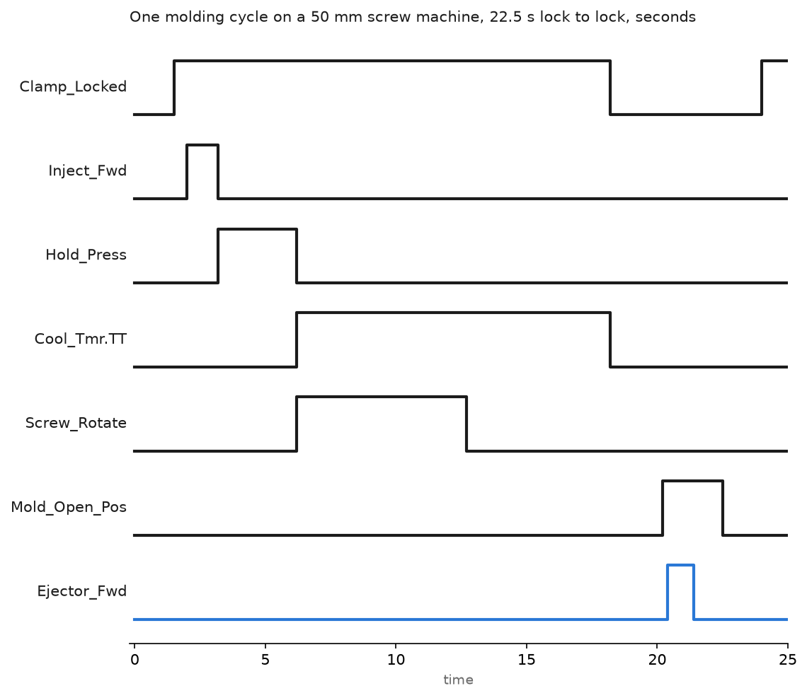
- Close, 0 to 1.5 s. Fast close, then slow at low pressure inside the mold protection window. If the clamp misses the lock position within the window time, a part is still in the cavity and the cycle stops with a reason code.
- Lock and inject, 1.5 to 3.2 s. High pressure lock, nozzle contact check, then the fill profile: 1.2 s on this job in five velocity stages by screw position, with the switch to hold at a screw position, not a time.
- Hold, 3.2 to 6.2 s. Pressure control on the second analog output, 3 s in two stages.
- Cool, 6.2 to 18.2 s.
Cool_Tmrruns 12 s. Screw recovery runs inside the cooling time, 6.5 s here, followed by decompression. Cooling is the step production wants shortened; the interlock below stops that going wrong. - Open, 18.2 to 20.2 s, and eject, 20.4 to 21.4 s. The robot takes the part between 21.4 s and 22.5 s, drops the mold area free signal back in, and the next close starts at 22.5 s.
(* IMM_Cycle routine, 20 ms periodic task, Studio 5000 v33, CompactLogix 5380 *)
(* Steps: 10 close, 20 lock+inject, 40 hold, 50 cool, 60 open, 70 eject, 80 robot *)

Hold_Tmr.PRE := Recipe.HoldTime_ms;              (* 3000 on this job *)
Hold_Tmr.TimerEnable := (Cycle_Step = 40);
TONR(Hold_Tmr);

Cool_Tmr.PRE := Recipe.CoolTime_ms;              (* 12000 on this job *)
Cool_Tmr.TimerEnable := (Cycle_Step = 50);
TONR(Cool_Tmr);

CASE Cycle_Step OF
    40:  (* hold pressure, then hand over to cooling *)
        Hold_Press_Cmd := 1;
        IF Hold_Tmr.DN THEN
            Hold_Press_Cmd := 0;
            Cycle_Step := 50;
        END_IF;
    50:  (* cool, screw recovers in parallel until the shot is ready *)
        Screw_Rotate_Cmd := NOT Shot_Ready;
        IF Cool_Tmr.DN AND Shot_Ready THEN
            Cycle_Step := 60;
        END_IF;
    60:  (* open to the recipe position *)
        Clamp_Open_Cmd := 1;
        IF Mold_Open_Pos THEN
            Clamp_Open_Cmd := 0;
            Cycle_Step := 70;
        END_IF;
    70:  (* eject only with the area free and the robot's enable *)
        Ejector_Fwd_Cmd := Mold_Area_Free AND Robot_Eject_Enable;
        IF Ejector_Fwd_Pos THEN
            Ejector_Fwd_Cmd := 0;
            Cycle_Step := 80;
        END_IF;
END_CASE;

IF Guard_Open OR NOT Safety_OK THEN
    Cycle_Step := 0;     (* GuardLogix already dropped the outputs; keep the sequence honest *)
END_IF;

Rung 40 is the same interlock drawn as ladder with the tag names shortened to fit; in the project they are Mold_Open_Pos, Cool_Tmr.DN, Mold_Area_Free and Robot_Eject_Enable. The cooling done bit sits in the ejector rung on purpose: an operator can lower the cooling time on the HMI, but nothing lets the ejector move before the timer has expired and the mold is open. When the sequence outgrows a CASE, the same steps map onto an SFC, see implementing sequential function charts in PLC programming.
Control the barrel zones and check the thermocouples twice
Each zone is a PID with a time-proportioned output: the PID writes 0 to 100 percent and a 1 s cycle on this machine turns that into an SSR on-time. A molding barrel is heat only; an extruder barrel adds fans on the front zones because the screw puts in shear heat that has to come out. The nozzle zone gets a tighter band and its own soft-start, because that small heater burns out first. PID structure and tuning are in implementing PID control in PLC systems.
The checks matter more than the tuning does.
- Card level. The thermocouple module’s open-wire and over-range flags force that zone’s output to zero and raise an alarm. Never let an open thermocouple read as a low temperature, because the PID will drive the heater flat out.
- Plausibility between zones. Neighbouring barrel zones on this machine stay within 60 C of each other in normal running. A zone reading 80 C above its setpoint with the output at zero means a shorted SSR, and the PLC drops the heater contactor for the whole barrel. The contactor exists for this case.
- Loop break. Output at 100 percent for 5 min with the temperature rising less than 3 C means a burnt heater band or an SSR that failed open. Alarm, do not trip, the melt is still there.
- Soak before rotation. Screw rotation and injection stay locked until every zone has held within 5 C of setpoint for the recipe soak time, 15 min here. Cold material in the barrel snaps screws.
Extrusion uses the same zone logic on a longer barrel and adds two loops the molder does not have: melt pressure at the die with a hard trip below the transducer rating, and haul-off speed as a ratio of screw speed so wall thickness holds when the operator changes rate.
Know what the PLC commands on hydraulic and electric machines
On the hydraulic machine the PLC writes two analog setpoints per phase – pressure and flow – to the proportional valve amplifiers, and reads linear transducers for position. Servo-hydraulic adds a speed reference to the pump motor drive so the pump idles between phases, which is where the energy saving comes from. On an all-electric machine every movement is a motion axis: the injection axis runs a velocity profile and switches to torque limiting at the hold point, the same problem as a servo press. The motion side is in PLC motion control.
Wire the guards and the robot the way the standard expects
EN 201 is the C standard for the machine: it names the safety functions around the mold area and the performance level each must reach under ISO 13849-1, and the builder’s risk assessment covers only what the standard leaves open. PLd with Category 3 architecture is what you meet most often on this class of machine, two monitored channels from the guard, plus the monitored hydraulic safety valve and the mechanical restraint that EN 201 asks for on a hydraulic clamp. The GuardLogix holds the enables for clamp close, injection and ejector; the sequence PLC asks, the safety PLC allows.
Where a robot or conveyor prevents a fixed guard, the part removal area is a light curtain zone. Muting is the temptation and the audit finding: mute only while the mold is open and the robot is inside its own envelope, and log every mute.
The robot talks EUROMAP 67, a hardwired 50-pin interface: mold area free, safety devices operational, mold open position, ejector enable, core puller enable, reject. Robot_Eject_Enable in the code above is one of those wires; EUROMAP 79 is the OPC UA version of the same robot interface, still rare on the floor. EUROMAP 77 carries shot counter, cycle time and job data to the MES over OPC UA; older presses use EUROMAP 63 session files on a shared folder, which still works and still needs someone to watch the folder. The MES side is in integrating PLC with MES, and the interlock structure in implementing PLC safety interlock systems.
Change what has to change for rubber
The thermal picture flips. A rubber press keeps the barrel and runner cool so the compound does not scorch, 80 C on this press, and the mold hot, 170 C, because the mold is where the cure happens. The cooling timer becomes a cure timer set from the compound’s rheometer curve and corrected on the HMI for mold temperature; the correction factor comes from the rheometer data, not from the PLC.
Upstream, the internal mixer is a batch sequence: ram up, charge the polymer and the carbon black from the weigh hoppers, ram down, mix, add oil, mix again, drop door. The drop condition is batch temperature or integrated drive energy, and the PLC sums kW from the drive to get the kWh. Calendering is a tension and gap problem: roll gap servo-positioned against a thickness gauge, take-off tension closed on a load cell or a dancer. Recipe handling for compounds follows the structure in PLC batch process control.
Field notes
Soak interlock bypassed. A setter forced the soak bit to get a machine running after a weekend. The screw sheared at the feed section on the second rotation, and the force was still in the controller a month later. Forces on interlocks now trip a permanent HMI banner, and the soak time lives in the recipe: shorten yes, skip no.
Shorted SSR with no contactor. Zone 2 on an older extruder climbed past 400 C while the controller showed zero output. The SSR had failed closed, nothing in series could open, and the heater band melted its own terminals. Every heater circuit now has a contactor that drops on any zone 40 C over setpoint, driven from a rung that does not depend on the PID.
Ejector forward with the robot inside. A relay interface built by a previous integrator pulsed the ejector from the robot’s cycle-done output instead of using the EUROMAP 67 mold area free and ejector enable wires. The robot arm took a hit when the cycle-done fired early after a program edit. The interface was rewired to the standard pinout and the ejector rung rebuilt as above.
Frequently asked questions
Why not switch to hold on time?
Melt viscosity changes with regrind ratio, moisture and barrel temperature. Screw position at switchover tracks the actual shot; time does not. Cavity pressure is better still if the mold carries the sensor.
Can a standard PLC run the whole machine?
Yes for a retrofit or a small press. New high-speed machines run vendor controllers that close the injection velocity loop faster than a general PLC. Use the PLC for sequence, heating, safety and data, and let the axis controller own the profiles.
Does EUROMAP 77 replace EUROMAP 63?
On new machines yes. EUROMAP 63 stays on the floor for years because everything can read a file. Plan for both.
Next step
Get Cycle_Step, the shot counter and the zone temperatures into a historian before someone asks, with the method in best practices for PLC data logging.