ESTOP and Its Two Reset Inputs: What a Safety Reset Actually Requires
An ESTOP instruction on a GuardLogix 5580 sitting with Fault Present on and Inputs Inconsistent on will ignore the blue button on the panel for as long as that button is wired to the Circuit Reset operand. Circuit Reset energises Output 1, Fault Reset clears faults, and the 500 ms the instruction allows its two channels to disagree is fixed with no operand anywhere to change it. Those are the two facts the rest of this follows from, and the second one decides whether ESTOP is the right instruction for your device at all. What a reset actually requires, then, is this: no fault present, both channels in the active state, and an off-to-on transition of Circuit Reset. If any fault is standing, that sequence has to be preceded by an off-to-on transition of Fault Reset with the underlying condition already gone. Operands and behaviour below are from 1756-RM095O, September 2025, on a GuardLogix 5580.
Both channels are normally open here. Zero on both is safe, one on both is active, and there is no complementary option.
Two reset inputs, and what each one will and will not do
Circuit Reset only ever energises Output 1. It cannot clear anything.
Fault Reset only ever clears faults, and only when the condition that caused the fault has already gone away; it does not energise Output 1 by itself. On a panel with one reset button that means one of two things. Either you feed both operands from the same one-shot bit and accept that a single press clears the fault and then, on the next press, energises the output, or you build the two conditions separately in logic and give the maintenance case its own path. The first is what most projects do and it is why a stuck E-stop produces the complaint that “the reset needs pressing twice”, which is not a fault, it is the instruction behaving as documented. What makes it confusing on a live machine is that the panel usually has one lamp, and Fault Present, Inputs Inconsistent, Cycle Inputs and Circuit Reset Held On are four separate output bits with four separate meanings, all of which end up driving the same lamp because nobody wanted four. Bring them to the HMI individually. Each one names a different thing for the operator to go and do, and the difference between “press and release the reset” and “open and close the guard” is the difference between a thirty-second call and a two-hour one.
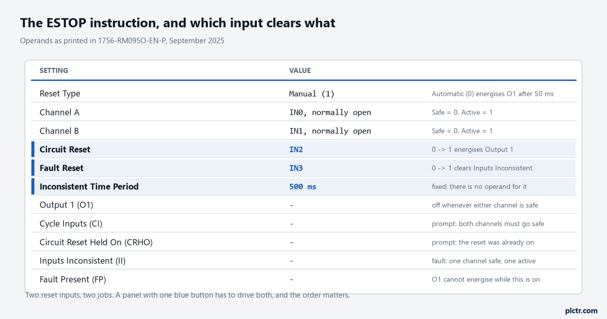
Circuit Reset and Fault Reset are highlighted because they are the two the drawing usually merges. The 500 ms is highlighted because it is the one number here you cannot configure.
There is a third condition that catches people, and it has no reset input at all. If, while Output 1 is active, one channel goes to the safe state and comes back before the other channel goes safe, the instruction sets the Cycle Inputs prompt, and Output 1 cannot be energised again until both channels have been through their safe states together. No amount of pressing either reset button does anything. Somebody has to hit the E-stop properly and release it properly, which on a rope-pull with a sticky contact block is exactly the thing nobody thinks to try.
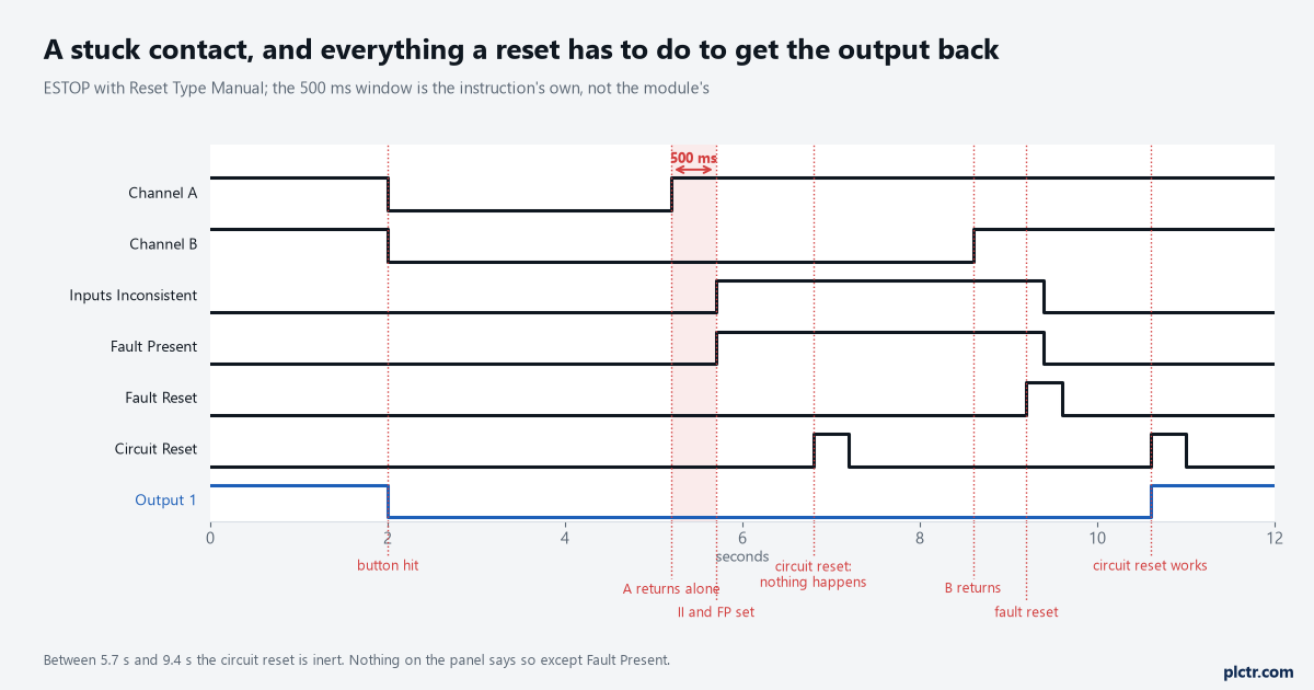
Between 5.7 s and 9.4 s the circuit reset is inert and the panel gives no sign of it. Fault Present is the only bit that says why.
The 500 ms you cannot change
Two channels in inconsistent states for longer than half a second is a fault, and that limit is written into the instruction.
Compare that with DCS, where Discrepancy Time is an operand with a range of 5 to 3000 ms, and the choice between the two instructions stops being a matter of taste. A twin-contact E-stop mushroom head with both blocks on the same actuator will break within a few milliseconds of each other, and 500 ms is enormous. A tongue interlock on a heavy door, a rope-pull over ten metres, or a pair of contacts in a device whose two elements are mechanically separated, can easily be slower than that, and then ESTOP will fault every time and nothing in the operand list will save you. Measure the gap on the actual device before you choose, trend both channels at the safety task period across ten operations, and pick the discrepancy time from the device rather than from a default. The other differences follow from the same era: DCS carries a Safety Function name for documentation, a Cold Start Type that decides what happens after a download, and a Fault Code output with distinct values, where ESTOP reports through individual bits. ESTOP is the instruction set that arrived with RSLogix 5000 version 14 and it is still certified and still applies to the current 5580 and Compact 5380 controllers, so an old project running it is not a project that has to be rewritten. A new one has a better default.
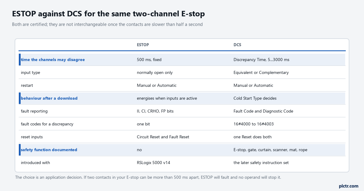
The top row is the one that decides. Everything below it is convenience.
A footnote that changed in September 2025
The reset-transition footnote under these instructions used to cite a requirement from ISO 13849-1. It no longer does, and the manual says why.
The Summary of Changes at the front of the September 2025 revision records that the footnote describing the need to monitor the transition of the Reset input was updated across most of the safety instruction topics, because earlier versions had described a requirement based on ISO 13849-1 and that standard has since been revised so that it no longer states it. What the footnote says now is softer and, for a designer, more work: some safety standards require the transition of the reset input to be monitored, and where the reset is resetting a safety function, additional logic may be needed to verify a transition from high to low or from low to high. That is not permission to wire a plain contact to Circuit Reset and move on. It means the obligation now comes from whichever standards your machine is being assessed against and from your own risk assessment, rather than from a line in a Rockwell footnote, and the safe engineering answer has not changed: build the edge, and build it in logic you can point at. The one-shot that does it, and the reason a held button is not a reset, is worked through in the rising-edge reset article. If you take one thing from the change, take this: the footnote you remember from an older PDF is not the footnote in the current one, and citing the old version in a design review is now a correction waiting to happen.
Verify it against your own application and your own assessment. An article cannot do that part for you, and neither can a footnote.
Automatic reset, and the sentence printed next to it
Set Reset Type to Automatic and Output 1 energises 50 ms after both channels reach the active state, with Circuit Reset visible in the instruction but unused.
The manual prints a warning beside the automatic-reset wiring example rather than a note, and it names EN 60204 and ISO 13849-1 as standards that require other measures to be in place, when the automatic circuit reset feature is used, to make sure an unexpected or unintended startup cannot occur. Which is the whole design problem in one sentence: automatic reset on the instruction does not mean automatic restart of the machine, and if the machine does restart on its own because the instruction’s output went straight into a contactor, the instruction did what you configured and the design did not. Automatic is right where the reset is genuinely happening elsewhere in the safety circuit, typically at the output function, and wrong almost everywhere else.
The thing everyone checks first
The E-stop station. It gets swapped, and the new one does the same thing.
A better order: read Fault Present and Inputs Inconsistent before touching anything, because those two tell you whether the instruction is faulted or merely waiting. If Cycle Inputs is set, the answer is an operation of the device, not a reset. If Circuit Reset Held On is set, the reset input was already on when the channels went active, which is a taped button, a jumper, or a mapped HMI bit that nobody clears. If Inputs Inconsistent is set, trend both channels and see which one is late, and then look at the module’s input configuration, because a point left as Equivalent or Complementary instead of single hands the instruction results it was not expecting; the instructions supply the dual-channel handling themselves and the reference manual asks for the points to be set single. Only when all four bits are clear and the output still will not come on is it worth thinking about the contactor feedback and the mirror contacts, which is a different instruction’s problem.
One more that costs an afternoon. On a false rung every ESTOP output is zero, including the prompts and the fault bits, so an instruction conditioned by something that is false looks perfectly healthy and tells you nothing.
Next step
Take the E-stop you have and measure the gap between its two contacts opening, ten times, trended at the safety task period. If the worst gap is comfortably inside 500 ms, ESTOP is a legitimate choice and the rest of the work is separating the two reset inputs and bringing the four prompt bits to the HMI as four different messages. If it is not, or if you want the fault codes and the cold-start behaviour, the instruction you want is DCS, and the discrepancy time you set on it is the subject of the next article in this set, along with the two fault codes that have no timer behind them at all.