The guard on the case packer closed at 14:07 and the infeed conveyor started on its own, with the blue reset button 4 m away and nobody within reach of it. The DCS instruction on that gate was configured Restart Type Manual, exactly as the drawing said, and the machine still restarted, because the button had been taped down since the morning changeover and the rung that fed the instruction’s Reset operand was a plain XIC of the input. A taped button is a level. Manual restart needs a safety reset rising edge, and there was never going to be one. The one rung is a one-shot on the release of the reset button, qualified by how long the button was held, feeding the Reset operand of the safety instruction and nothing else. It costs a timer and a storage bit, and it turns a jumper, a taped button or a held HMI bit from a restart into a diagnostic code. Everything below is a GuardLogix 5580 with a 1791ES-IB8XOBV4, the gate on a DCS instruction, contactors on a CROUT, and then the same rule on a Siemens F-CPU with ESTOP1 and SFDOOR, where the block asks for the edge by name.
What “manual restart” is actually promising
That closing the guard does not start the machine. The operator does.
Rockwell’s Safebook 5 quotes ISO 12100 for the principle – when the guard is closed the hazardous functions can operate, but the closure of the guard does not by itself initiate their operation – and its description of a monitored manual reset is the mechanism: a change of state of the reset circuit is required after the gate is closed or the E-stop released, so that the reset function proves the contactors are off, the interlock circuits are closed, and, because a change of state is required, that the reset actuator has not been bypassed or blocked. The Safebook adds that ISO 13849-1 cites the change of state from energised to de-energised, the falling edge, for that additional manual reset. I have not read the standard; that is Rockwell’s summary of it, and it is the reason the rung below acts on the release rather than the press. The same document is blunt about the alternative, a relay with automatic/manual reset where the reset is not monitored: a short-circuited or jammed-in reset switch will not be detected.
A change of state after the guard closes: that is the whole of the definition.
In the DCS instruction that promise is one operand. 1756-RM095 defines Restart Type Manual as: a transition of the Reset input from OFF to ON, while all of the Output 1 enabling conditions are met, is required to energise Output 1. Automatic energises Output 1 50 ms after the enabling conditions are met, with an attention note that it may only be used where you can prove no unsafe condition can occur or the reset function is performed elsewhere in the safety circuit. So the instruction itself already wants an edge. Then there is the footnote under the Reset operand, and it is the whole reason this article exists: some safety standards require monitoring the transition of the reset input, and when the reset is used to reset a safety function, additional logic may be required to verify a transition from high to low or low to high.
The instruction checks for a rising edge at the moment the inputs return. It does not check that the button was ever released.
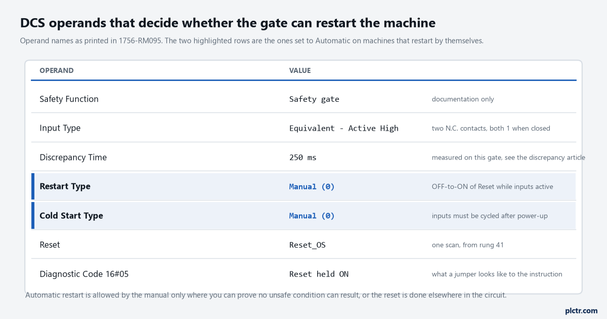
Restart Type and Cold Start Type are the two operands found set to Automatic on machines that restart by themselves. The Reset row is the one this article is about: the operand takes the one-shot, never the raw input.
How a Manual restart still restarts by itself
Four ways, and the taped button is only the most obvious.
The first is the case at the top: the button held, or jumpered, or an HMI reset bit written to 1 and never cleared. With the input already at 1 when the guard closes there is no OFF-to-ON transition and the DCS does not restart – what it does instead is report Diagnostic Code 16#05, Reset input held ON, which is the manual telling you a level is not a reset. That is the well-behaved case. The machine that restarted at 14:07 was not on the DCS’s reset at all; somebody had written their own restart permissive downstream, XIC Gate_Closed XIC Reset_PB OTE Run_Permit, and a level on Reset_PB with the gate closing is a rising edge on the rung, which restarts everything the rung feeds. Every place a reset is evaluated as a level is a place the machine restarts when the other condition arrives.
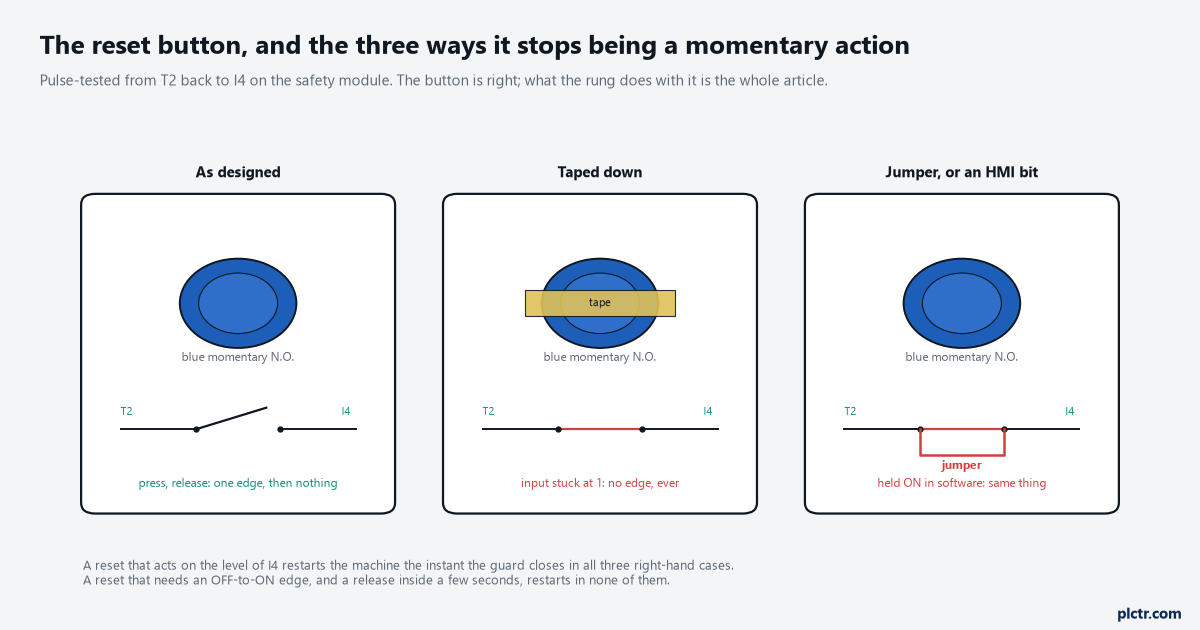
All three right-hand cases present the same thing to the controller: an input at 1. A rung that needs an edge treats them identically, and it treats a real press differently.
The second is Restart Type Automatic, left from a test or a copied routine, and the symptom is exact: the machine runs 50 ms after the guard closes, every time, with no reset involved. The third is Cold Start Type Automatic, which 1756-RM095 says energises Output 1 as soon as the Input Status becomes valid for the first time with the inputs active – so a controller powered up with the gate closed starts the machine with nobody touching anything, once, at power-up, and the fault gets written off as a power glitch. The fourth is the standard program. The safety output drops, the drive stops, the guard closes, the operator presses reset properly, the safety output returns, and the drive restarts immediately because the standard run latch was never cleared; the Siemens programming guideline says it in one line, the relevant safety standards require that a reset of the safety function does not trigger a restart of the machine, and its recommendation is to interlock the process control in the standard program with the enable signal from the safety program so that a safe shutdown also resets the process control. The interlock article on this site lists that one as the failure it found on a real machine, and the fix is one XIO of the safety output in the run latch.
Two of the four are configuration. One is the rung. One is the standard program.
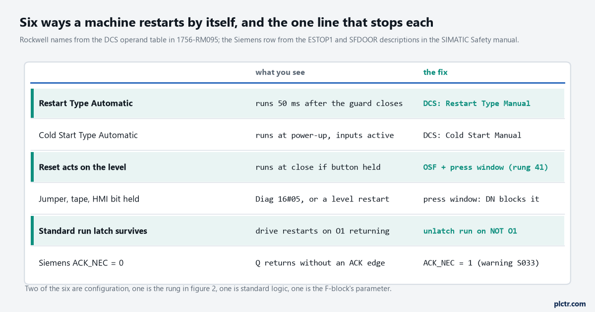
The four above, plus the level rung that turns a held button into a restart and the Siemens parameter that is the same thing as Restart Type Automatic. Each has a symptom you can see on a trend before you touch anything.
The one rung that makes it a safety reset rising edge
A one-shot on the release, allowed only if the press was long enough to be a hand and short enough not to be tape.
(* SafetyTask - reset qualification for gate 1 *)
Reset_Held.PRE := 3000;
Reset_Held.TimerEnable := Reset_PB;            (* I4, pulse-tested from T2 *)
TONR(Reset_Held);
IF NOT Reset_PB THEN Reset_Held.Reset := 1; END_IF;

(* one scan on the release, and only for a press between 80 ms and 3 s *)
Reset_OS := (NOT Reset_PB AND Reset_PB_Last)
            AND NOT Reset_Held.DN
            AND (Reset_Held.ACC > 80);
Reset_PB_Last := Reset_PB;
Three things happen in those lines. The falling edge is the change of state the Safebook describes and the transition the RM095 footnote asks you to verify: nothing about the button being at 1 produces Reset_OS
Reset_Held.DN staying true is a fault you put on the HMI. In ladder it is the same three rungs, and the DCS’s Reset operand takes Reset_OS, not Reset_PB.Release, not press. Between 80 ms and 3 s. One scan, and then nothing.
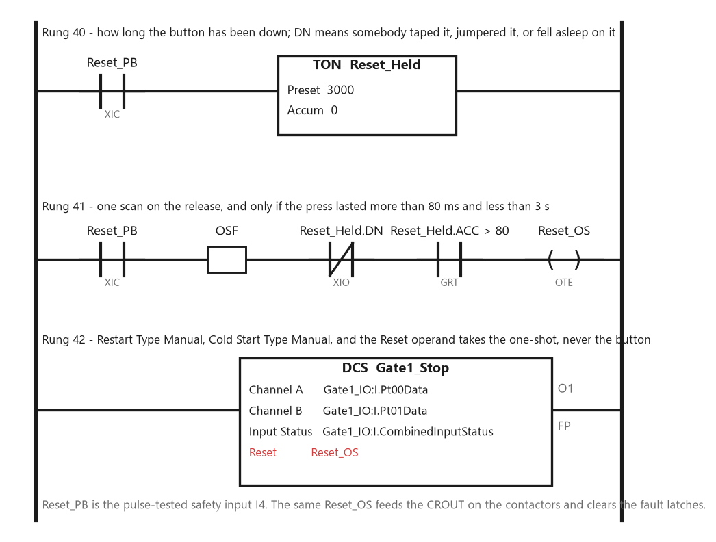
Rung 41 is the article. The DCS on rung 42 sees a single scan of Reset_OS on a valid release and nothing at all on a held, taped or jumpered button.
One thing 1756-RM018 says about one-shots belongs here, because it decides what happens on the first scan. An ONS or OSR sets its storage bit true during prescan to prevent an invalid trigger on the first scan; the ST version above does the same job with Reset_PB_Last, which must be initialised to the current input on the first pass or a controller powered up with the button somehow at 0 and the last-state at 1 fires a release that never happened. Give it the input’s value in the first-scan routine and forget about it.
Initialise the last-state bit on the first scan, then leave it alone for good.
And the same Reset_OS goes everywhere a reset is needed: the DCS on the gate, the CROUT on the contactors, the fault latches. One edge, produced once, consumed by every instruction that wants one. Two different reset rungs for two instructions is how one of them ends up reading the level.
What it looks like on a trend
Put Reset_PB, both gate channels, Reset_OS and the DCS Output 1 in one trend at the safety task period and run the test that matters: press and hold the button, open the guard, close it, keep holding, then let go.
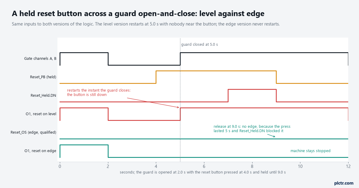
Gate closed at 5.0 s with the button already down. The level version restarts at 5.0 s. The edge version sees a 5 s press, blocks it on Reset_Held.DN, and stays stopped until somebody presses and releases the button properly.
The level version restarts at 5.0 s with the operator’s hand still on the button and their eyes wherever they were looking. The edge version does nothing at 5.0 s and nothing at 9.0 s either, because the press lasted five seconds and the timer’s done bit blocked the release. It restarts on the next press-and-release, which is the operator, standing where the Safebook says the reset button belongs – with a good view of the hazard – deciding that it is clear. That trend is the acceptance test for the reset function and it takes four minutes.
Hold the button through the whole cycle. If anything starts, the rung is wrong.
The same rule on a Siemens F-CPU
STEP 7 Safety asks for the edge by name, in the block description itself.
The ESTOP1 description in the SIMATIC Safety manual reads: enable signal Q is reset to 1 not before input E_STOP takes signal state 1 and an acknowledgment occurs; with ACK_NEC = 1 you must use a rising edge at input ACK. SFDOOR is stricter still – the enable can only return if both inputs went to 0 before the door was opened, which is the door being fully opened, then both went to 1, then the acknowledgement – and it carries OPEN_NEC to demand the same at startup. Both blocks set ACK_REQ to tell the standard program that an acknowledgement is being waited for, and both carry warning S033: ACK_NEC must not be 0 unless an automatic restart of the affected process is otherwise excluded. So ACK_NEC = 0 is the Siemens spelling of Restart Type Automatic, and it is the first thing to read on a machine that restarts by itself.
The block wants a rising edge on ACK, so the 80 ms to 3 s window goes in front of it exactly as it does in front of the DCS, and the block will not accept a held ACK twice.
The HMI case is where Siemens is more careful than most standard programs. The programming guideline’s ACK_OP system block takes an acknowledgement from the HMI in two steps – the IN parameter set to 6 for exactly one cycle, then to the ACK_ID value within one minute for exactly one cycle – and the guideline explains that the block resets IN to 0 every cycle, so an HMI tag copied into it every scan by the standard program breaks the one-cycle condition and the acknowledgement never happens. That is a level being refused by design. A reset bit on a PanelView written by a button’s momentary push and cleared by the same button’s release, mapped into the safety task and one-shotted there, is the Rockwell equivalent, and 1756-RM012 shows the latch that goes with it: a standard input mapped into safety must be qualified with safety data and latched so that a standard tag stuck at 1 cannot cause an automatic restart. The manual’s own example is a reset.
A level refused by design, in both vendors’ own worked examples.
The thing everyone checks first
The button, and it is the fourth thing on the list.
The station gets opened, the contact block gets checked for continuity, the block gets swapped, and it changes nothing because the button was doing what buttons do. The first thing to read is the instruction: Restart Type and Cold Start Type on the DCS, ACK_NEC on the F-block, and whether the operand called Reset is fed from the raw input or from a one-shot. The second is the trend above, which takes four minutes and answers the question for every cause at once. The third is the standard program’s run latch, because a machine can pass the trend on the safety output and still restart the drive from a latch that was never unlatched. The button is fourth, and by then it is usually the tape.
Read the operand before you open the station, and trend before you swap anything.
Next step
Find every place in the project where the reset input is referenced – the cross-reference on Reset_PB should show exactly one rung, the one that makes Reset_OS – and move anything else onto the one-shot. Then run the held-button trend on every safety function on the machine, not only the gate, because the E-stop’s DCS and the contactors’ CROUT each have their own Reset operand and each one can be fed from the wrong place. The contactor feedback that the same one-shot resets is in EDM and the mirror contact, the two-channel input the DCS is evaluating in discrepancy time on a dual-channel safety input, the complete gate and E-stop function in the dual-channel interlock walkthrough, and whether the machine wants a controller or a monitored-reset relay in the first place in the relay-or-controller article.
One edge, made once, consumed everywhere a reset is needed on the machine.