A 1606-XLE240E Series B has a DC-OK relay on terminals 13 and 14 that closes while the 24 V bus is above 90 % of its set point, and a Raspberry Pi 4 needs 5.1 V and somewhere between five and twenty seconds of notice to halt without corrupting its card. Raspberry Pi panel power is those two facts joined by one twisted pair and one line in config.txt, and it is the part people leave out because the Pi seemed to run fine off a phone charger on the bench. It does. It also runs fine off the panel rail, right up to the first time a contactor drops the mains for 200 ms and the Pi comes back with a read-only filesystem.
The short answer: feed the Pi from a DIN-rail 24 V to 5.1 V converter on its own 2 A branch fuse, take the supply’s DC-OK contact – or the buffer module’s buffering signal, if a buffer is fitted, and that distinction is most of this page – into a GPIO with the gpio-shutdown overlay, and size the buffer against how long your Pi actually takes to halt, which you measure once.
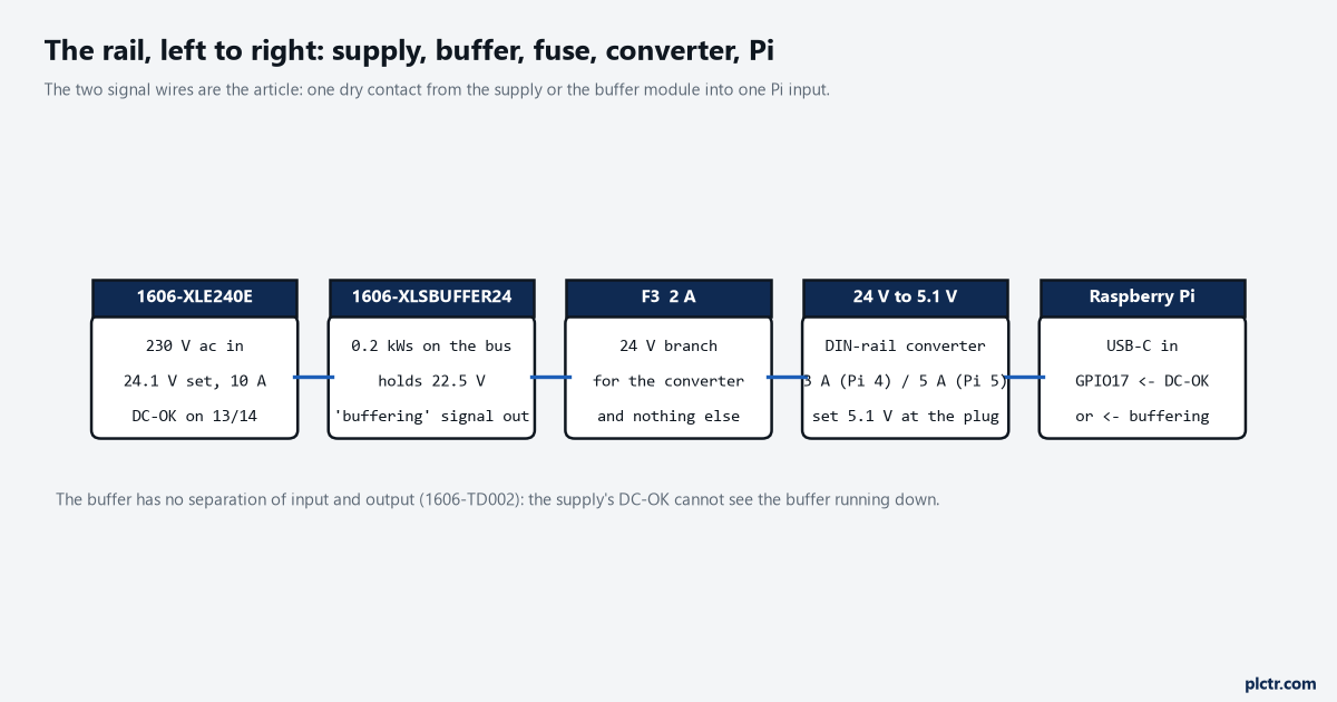
Five things on the rail and two signal wires. The note under the figure is the trap: the buffer has no separation between its input and output, so the supply’s own DC-OK cannot see the buffer running down.
Which supply actually has the contact
Start at the label on the supply, because the technical data and the installation sheet disagree.
Publication 1606-TD002H, the July 2023 specifications for the whole Bulletin 1606 range, has a “DC OK Relay Contact” row under the 1606-XLE Essential supplies, and for the 240 W column it reads none for -XLE240E and -XLE240EP, yes for -XLE240EC, -XLE240EL and -XLE240EH. The 120 W column is the same shape: none for the plain -XLE120E, yes for the spring-clamp and push-in variants. Read that and you order the conformal-coated or the push-in unit to get the contact. Then open 1606-IN039A, the June 2020 installation instructions for the 1606-XLE240E SER B and -XLE240EC SER B, and the functional description says the DC-OK relay monitors the output voltage, the contact is closed when the DC-OK LED is on, the functional diagram draws it on terminals 13 and 14, and the wire table gives the DC OK terminals as AWG 24-16. The Series B plain unit has the contact. What the TD row describes is, as far as I can tell, the earlier series, and nothing on the page says so. So the check is the series letter printed on the unit, not the catalog number, and if the panel was built before 2020 and the label reads Series A, assume there is no contact until you see terminals 13 and 14 with your own eyes. The one-line rule that settles it either way: if there are two small terminals marked 13 and 14 next to the output pair, you have the contact.
The threshold is in the same sheet. The green DC-OK LED reports an output voltage above 90 % of the adjusted voltage, and the relay follows the LED. Factory setting is 24.1 V, so the contact opens at about 21.7 V. Contact rating is 60 V dc at 0.3 A, 30 V dc at 1 A, 30 V ac at 0.5 A for resistive loads, which is a thousand times more than a GPIO input with a pull-up will ever draw through it.
The four wires of Raspberry Pi panel power
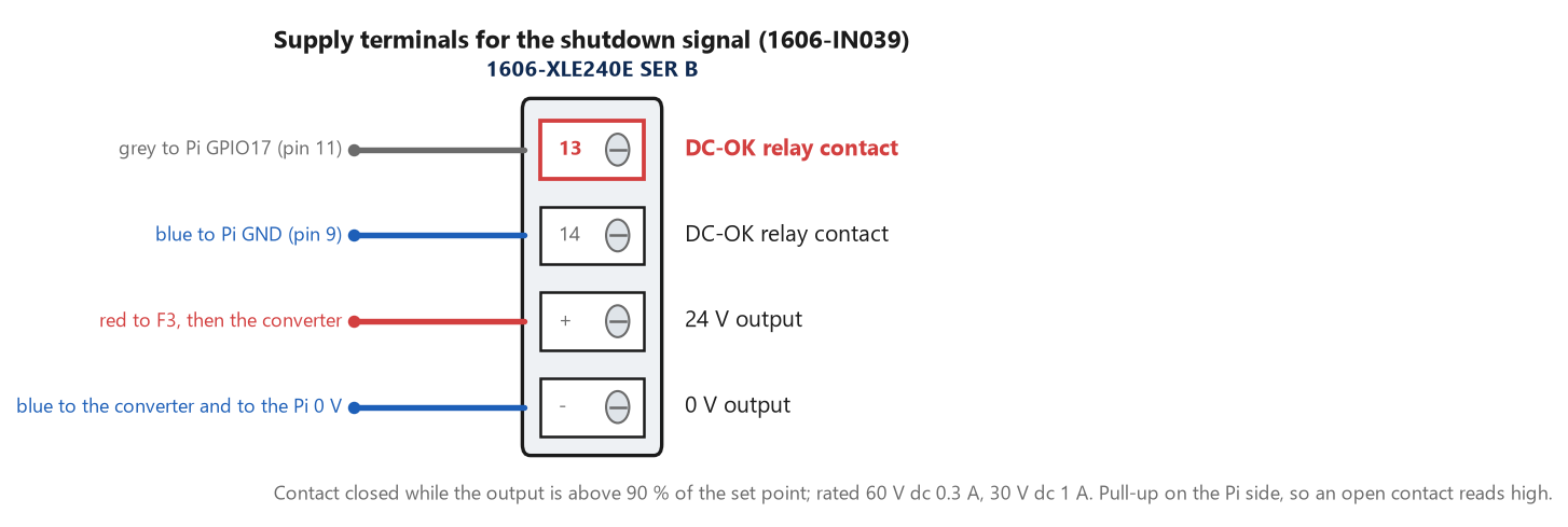
Terminal 13 to GPIO17, terminal 14 to a Pi ground pin. Closed while the bus is good, so with the Pi’s pull-up enabled the pin reads low in normal running and high the moment the contact opens.
Two wires carry the power and two carry the signal, and the pin number matters more than the wire.
The power pair runs from the supply’s + and – through a 2 A branch fuse to the converter’s input; a Pi 5 at its 25 W rating is a little over 1 A at 24 V once the converter’s losses are in, so a 2 A fuse clears a converter fault without nuisance-tripping on the input capacitor’s inrush, and it keeps the Pi’s fault from taking down whatever else shares the rail. The signal pair is the dry contact: terminal 13 to a GPIO, terminal 14 to a ground pin on the header. A relay contact is not a voltage, so the Pi’s own pull-up defines the idle level and there is nothing to level-shift. The pin matters. The overlay defaults to GPIO3, and the firmware README says the board can be powered up again after shutdown by driving GPIO3 low – which is a feature for a push button and a problem for a contact that closes every time the bus recovers, because the Pi would be told to wake in the middle of the power dip it was shutting down for. GPIO3 also carries a fixed pull-up as an I2C line. Pick GPIO17, or any plain pin with no second job. The converter itself: 3 A continuous for a Pi 4, 5 A for a Pi 5, set to 5.1 V, and the documentation’s own sentence is that all models require a 5.1 V supply. A converter trimmed to a round 5.0 V with a long USB-C lead lands under 4.9 V at the board, and the Pi has detected under-voltage since the B+ in 2014 at 4.63 V plus or minus 5 %, writes it to the kernel log, and throttles. dmesg | grep -i voltage after a week tells you whether the lead is too long. One Pi 5 detail worth knowing before the converter is ordered: with a supply it recognises as 5 A over USB-C the board gives 1.6 A to its USB ports, and with any other supply it holds them to 600 mA. A plain DC-DC converter is “any other supply”, so a Pi 5 with a USB RS-485 adapter and a cellular modem hanging off it is on the 600 mA budget unless you find the setting that lifts it, and that is a question for the power-supply page on the Pi’s own site before the converter is ordered; a Pi 4 has no such limit and no such negotiation.
The overlay, and what the Pi does with the edge
One line in /boot/firmware/config.txt on current Raspberry Pi OS – /boot/config.txt on releases before Bookworm – and a reboot:
# DC-OK (or buffer 'buffering') dry contact: 13 -> GPIO17, 14 -> GND
# contact closed = bus good = pin low; open = shutdown
dtoverlay=gpio-shutdown,gpio_pin=17,active_low=0,gpio_pull=up,debounce=200
The firmware README describes gpio-shutdown as configuring the pin as an input key that generates KEY_POWER events, with gpio_pin defaulting to 3, gpio_pull defaulting to up, and debounce defaulting to 100 ms. active_low=0 means the rising edge is the key-down, which is what an opening contact produces against a pull-up. The 200 ms debounce is the same number the mains dip in the title has: a contact that flickers on a supply that is sagging and recovering should not fire the halt on the first bounce. From there it is not the overlay’s job any more. KEY_POWER is the same event a laptop’s power button raises, and systemd-logind handles it according to HandlePowerKey in /etc/systemd/logind.conf, whose default is poweroff. Check that file once, because a desktop image may have it set to ignore or suspend.
The dead end here is writing a Python script to poll the pin. It works, until the script is the thing that crashed, or the service that runs it was not enabled after the last image was flashed, or it is waiting on a lock held by the logger it is supposed to protect. The overlay puts the halt in the kernel and logind, which are running if anything is.
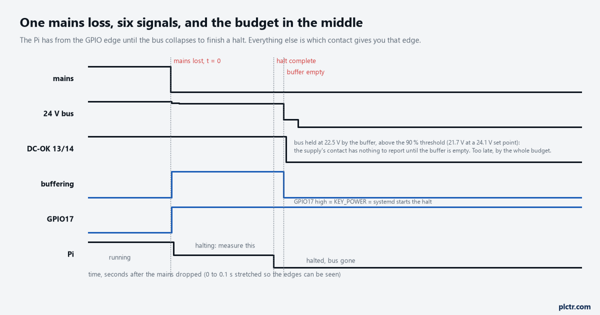
The whole design is the gap between the GPIO edge and the bus collapsing. On a buffered bus the supply’s contact stays closed until the buffer is empty, which is why the buffer’s own signal has to be the one on GPIO17.
Where the ride-through comes from, and the contact that lies on a buffered bus
The supply’s own hold-up is 37 ms, and that number is measured at 10 A.
1606-IN039 gives hold-up as 37 ms at both 120 and 230 V ac, at the sheet’s stated condition of 24 V 10 A output. A Pi and its converter draw about a twentieth of that, so the real hold-up on your rail is longer, and it is not specified anywhere I could find, so it is not a number to design with. What the 37 ms tells you is the shape of the problem: on the supply alone a mains dip of 200 ms is a full outage as far as the 24 V bus is concerned, and the DC-OK contact opens at 21.7 V somewhere near the end of that 37 ms, which leaves the Pi roughly nothing between the edge and the converter dropping out. That is the case without a buffer, and it is the case most panels have. A buffer module is what turns the edge into a budget. 1606-TD002 lists the 1606-XLSBUFFER24 as 0.2 kWs of electrolytic capacitors, 310 ms at 20 A, 22.5 V in buffer mode, 18 s to charge; the 1606-XLSCAP24-6 as 6 kWs of double-layer capacitors, 16.5 s at 10 A and 9 s at 15 A; the -XLSCAP24-12 as twice that. Scale the datasheet point to a 30 W load – a Pi 5 flat out plus converter loss – and the electrolytic module holds the bus for about 5 s, the 6 kWs one for about 2 min. Those two right-hand numbers are my arithmetic on the vendor’s points, not a test, and they are optimistic in one direction because the modules were characterised at heavy load and in the other because a bare Pi 4 is nearer 8 W. They are good enough to make the decision, which is: the XLSBUFFER24 buys you the signal edge and enough time for the filesystem to flush; it does not buy a leisurely halt. The XLSCAP24-6 buys the halt several times over.
Now the part the caption keeps repeating, because it is the one that gets wired wrong.
The TD’s own row for the XLSBUFFER24 reads “Separation of Input and Output: No”. It sits across the same 24 V bus as the supply’s output terminals and holds that bus at 22.5 V while it buffers, and 22.5 V is above the 21.7 V at which the supply’s DC-OK opens. So on a buffered bus, at the moment the mains goes, the supply’s contact has nothing to report – the voltage it monitors is fine – and it opens when the buffer runs out, which is the moment the bus dies. Whether the XLE’s monitor sits on the output terminals or behind an output diode, IN039’s one sentence does not say, and I have not put a scope on one to find out. The design does not need to know. Every buffer module in that table brings out its own signals, listed in the TD as ready, buffering and inhibit, and “buffering” is by definition the one that goes true at the instant the module starts supplying the bus. That is the contact for GPIO17 when a buffer is fitted. Its form and rating are in the module’s own installation instructions, which I did not read for this article, so check it against a 3.3 V pull-up before you land it. The -XLSCAP24-6 and -12, unlike the electrolytic module, are listed with separation of input and output, which changes the picture again: on those the supply’s DC-OK can see its own output collapse. It still is not the signal to use, because the buffer’s signal is true whichever module it is.
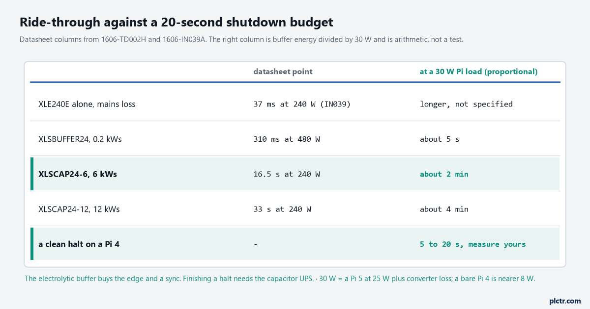
The right column is buffer energy divided by 30 W. The row that decides the buffer is the last one, and it is the one you have to measure yourself.
Measure the halt before you size anything
journalctl -b -1 -o short-precise | tail -n 40 after a test halt is the whole measurement.
The first line of the shutdown target and the last line before the journal stops are the halt time, and on a Pi 4 with a logger, a broker client and a database it is somewhere between five and twenty seconds, mostly spent waiting for services that were given 90 s to stop and take 9. Two things shorten it: a TimeoutStopSec= of a few seconds on the units you own, and a logger that commits often enough that there is nothing to flush – the SQLite queue commits once a cycle for exactly this reason, and the synchronous=NORMAL bet it makes is the bet this article’s buffer is there to cover. Then compare the halt time with the buffer column. If the halt is 6 s and the buffer is the electrolytic one, you are relying on the arithmetic being optimistic, and it might be. A read-only root filesystem is the other half of the answer: a card that is never written cannot be corrupted by a halt that did not finish, and the buffer only has to protect the one partition that is.
One thing this arrangement cannot do by itself is restart a halted Pi 4 after a short dip.
Mains returns at 300 ms, the buffer never emptied, the bus never dropped, the Pi finished its halt at 9 s and is now sitting halted on a perfectly good 24 V rail, and nothing will boot it until somebody cycles the converter. A Pi 5 behaves the same on its USB-C input. The honest fixes are a delay-off relay on the converter’s branch driven from the same buffering signal, or accepting it and putting a “logger halted” indication on the HMI from the controller’s side – a heartbeat tag the Pi’s poll loop increments and a TON that trips when it stops. Decide which before commissioning, because a Pi that is halted and looks healthy is worse than one that rebooted dirty.
Next step
Wire it, set debounce=200, and pull the mains breaker with a stopwatch running and journalctl -f on a screen. Note when the GPIO edge arrived, when the last journal line was written, and when the converter’s LED went out. Those three numbers, on your rail with your card, are the article; the datasheet points above only tell you which buffer to try first. Then unplug the Pi’s USB-C mid-write once, deliberately, and check the card with fsck afterwards, because that is the failure the whole page is insurance against and it is better to see it once on the bench than to wonder about it for a year. The timestamp article covers what a Pi 4 does with its clock across exactly this kind of outage, and it is the next thing that bites.