K1 and K2 are 100S-C09 safety contactors in series on a 4 kW conveyor motor, the CROUT that drives them holds Fault Code 16#5003 – both feedbacks ON with the outputs off – through every press of the reset button, and the suggestion at 06:10 was to raise the Feedback Reaction Time from 100 ms to the 1000 ms maximum until somebody could look at it properly. The fault was not the contactors. It was Feedback Type set to Positive with normally closed feedback contacts, which faults on the very first reset with two perfectly good contactors and looks exactly like a weld. The second call, a month later on a different machine, was a weld. External device monitoring is the safety logic checking, before it lets the contactors pull in again, that both of them actually dropped out last time. It only works if the contact it reads cannot lie about the power poles – which is what an EDM mirror contact is for, and what a snap-on auxiliary block is not. Everything below is a GuardLogix 5580 with a 1791ES-IB8XOBV4 driving two 100S-C09 contactors, the Siemens equivalent on an F-CPU with the FDBACK instruction, and a 440R relay where the same feedback goes into two terminals with no configuration at all.
What a welded pole looks like to the rest of the circuit
Nothing at all, and that silence is the whole of the problem.
Two contactors in series exist so that one welded pole does not keep a motor running; the other contactor still opens and the motor stops. Rockwell’s Safebook 5 puts it plainly for a Category 3 structure: a contactor can fail with welded contacts or a stuck armature, the second contactor removes power anyway, and the monitoring relay detects the faulted contactor on the next machine cycle because its mechanically linked contacts stay open and the relay cannot close its outputs. Without that detection the machine runs on with a single contactor doing the job of two, and the next weld is the one that does not stop. So EDM is not protection against the first fault. It is what stops the first fault from quietly becoming a single-channel system that nobody knows about. The detection depends entirely on which contact you read. The Safebook describes the requirement for mechanically linked contacts as the NC and NO contacts never being closed at the same time, with a welded NO leaving the NC open by at least 0.5 mm, and it names IEC 60947-4-1 as where that is defined. I have not read the standard; that is Rockwell’s summary of it, and the Siemens 3RT2 manual gives the same one-line definition for a mirror contact – an auxiliary NC contact that cannot be closed simultaneously with a main NO contact – under EN 60947-4-1 Annex F. A snap-on auxiliary block on a general-purpose contactor makes no such promise. Its NC contact is moved by the armature through a plastic linkage with clearance in it, and with one pole welded and the armature part-way, that NC contact can close. The feedback circuit then reports two healthy contactors while a motor sits behind one.
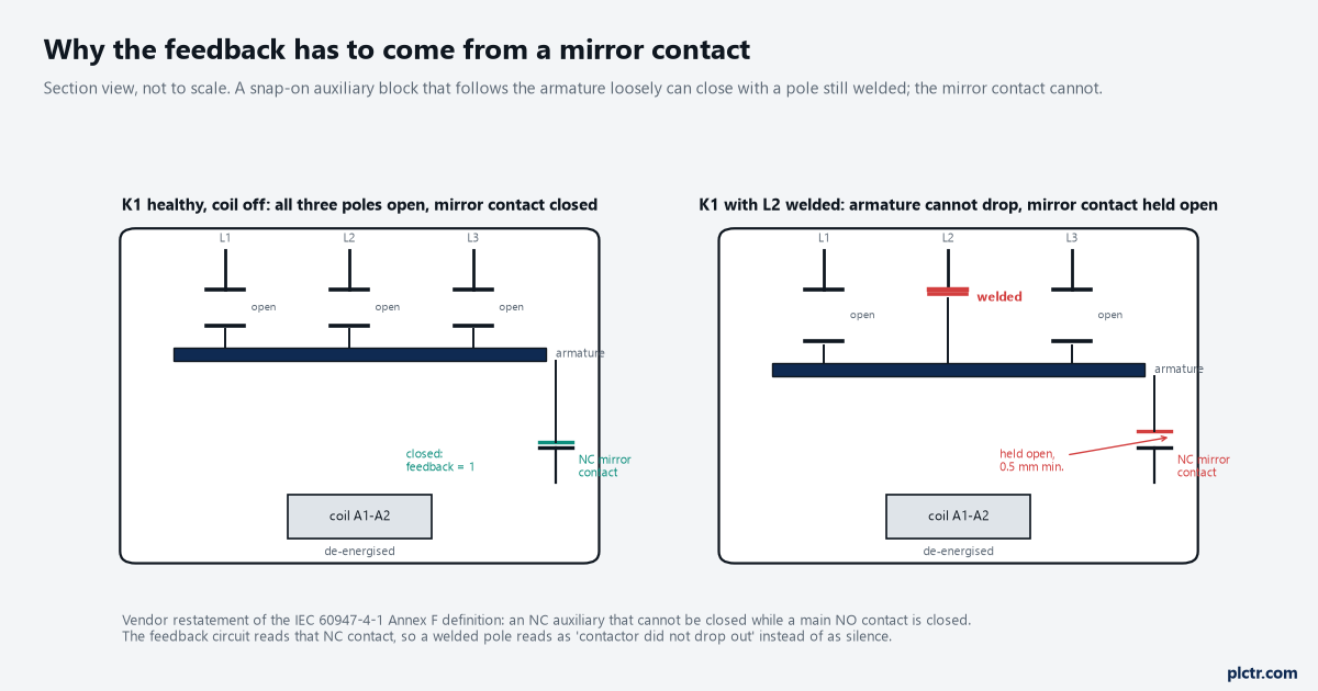
The feedback circuit reads the NC contact on the front. With L2 welded the armature cannot return, so the NC contact stays open by design and the logic reads “did not drop out” instead of silence.
Read the contact that cannot close. Not the contact that usually does not.
Mirror contact, mechanically linked contact, and which one your contactor has
Two terms, two standards, and the vendors are careful about which one they print on the front. A mirror contact belongs to a power contactor and is defined in IEC 60947-4-1 Annex F: the NC auxiliary against the main NO poles. A mechanically linked (positively driven) contact belongs to a contactor relay – a control relay with no power poles – and is defined in IEC 60947-5-1 Annex L: the NO and NC auxiliaries against each other. The 100S-C range in 100-TD013 lists both, “N.C. auxiliary contact meets mechanically linked performance per IEC 60947-5-1 Annex L” and “meets mirror contact performance per IEC 60947-4-1 Annex F”, and states the property in the words a feedback circuit cares about: the mechanically linked N.C. auxiliary contacts do not change state when a power pole welds. The same table lists what makes the block trustworthy rather than merely rated – the front-mounted contacts are permanently fixed, in a red housing, under a protective cover that prevents manual operation, with the mechanically-linked symbol on it. Siemens says the same of the 3RT2 range: tested to EN 60947-4-1 with mirror contact characteristics in conjunction with the auxiliary switches, and the SUVA requirement that the auxiliary switches are factory-mounted so they cannot be removed and that manual actuation of the contactor is not possible. Then the trap, in the same Siemens manual. The solid-state-compatible auxiliary switch blocks, 3RH2911-.NF.. and 3RH2911-.DE.., have no mirror contacts. Those are the blocks somebody fits when the feedback input is a PLC card and the standard block “chatters” – and the moment they are fitted the feedback circuit is reading a contact with no guarantee in it. The Rockwell answer to the same low-current problem is on the 100S-C itself: gold-plated bifurcated auxiliary contacts, which 100-TD013 describes as suited to low-energy feedback circuits with several NC contacts in series, so the mirror contact can switch a 24 V safety input directly.
The catalogue number tells you which you have. The front of the contactor tells you again.
The wiring: one EDM mirror contact per channel, pulse-tested
Each contactor’s NC mirror contact goes back to its own safety input, from its own test output. On the 1791ES-IB8XOBV4 that is T0 through K1’s NC contact to I2 and T1 through K2’s NC contact to I3, both inputs configured as Safety Pulse Test and single channel, so a short between the two feedback wires or a short to 24 V puts the wrong pulse train on one input and the module sees it. K1’s coil sits across bipolar output pair 0 and K2’s across pair 1, which is what the OBV4 suffix means – the module switches both the sourcing and the sinking side of each coil, and pulse-tests the outputs 700 µs wide every 600 ms while they are on, per 1791ES-UM001H. That pulse is far too short to drop a contactor, but the same manual’s note about the connected device’s input response time is the reason an interposing relay or a solid-state input placed between the safety output and the coil can misbehave: the pulse is meant for a coil. The series alternative is worth naming because it is what a safety relay does. Siemens’ safety programming guideline says the feedback circuit of both actuators in a redundant shutdown path must be evaluated and that they may be connected in series, and the MSR127’s feedback/reset loop on X1-X2 in 440R-TD001 is exactly that: K1 NC, K2 NC and the reset button in one loop, closed only when both contactors are out. That is correct and it is enough for the relay. On a controller with a two-feedback instruction, wire them separately, because the fault code then says which contactor to go and look at.
Separate feedbacks cost one input each and save an hour of guessing.
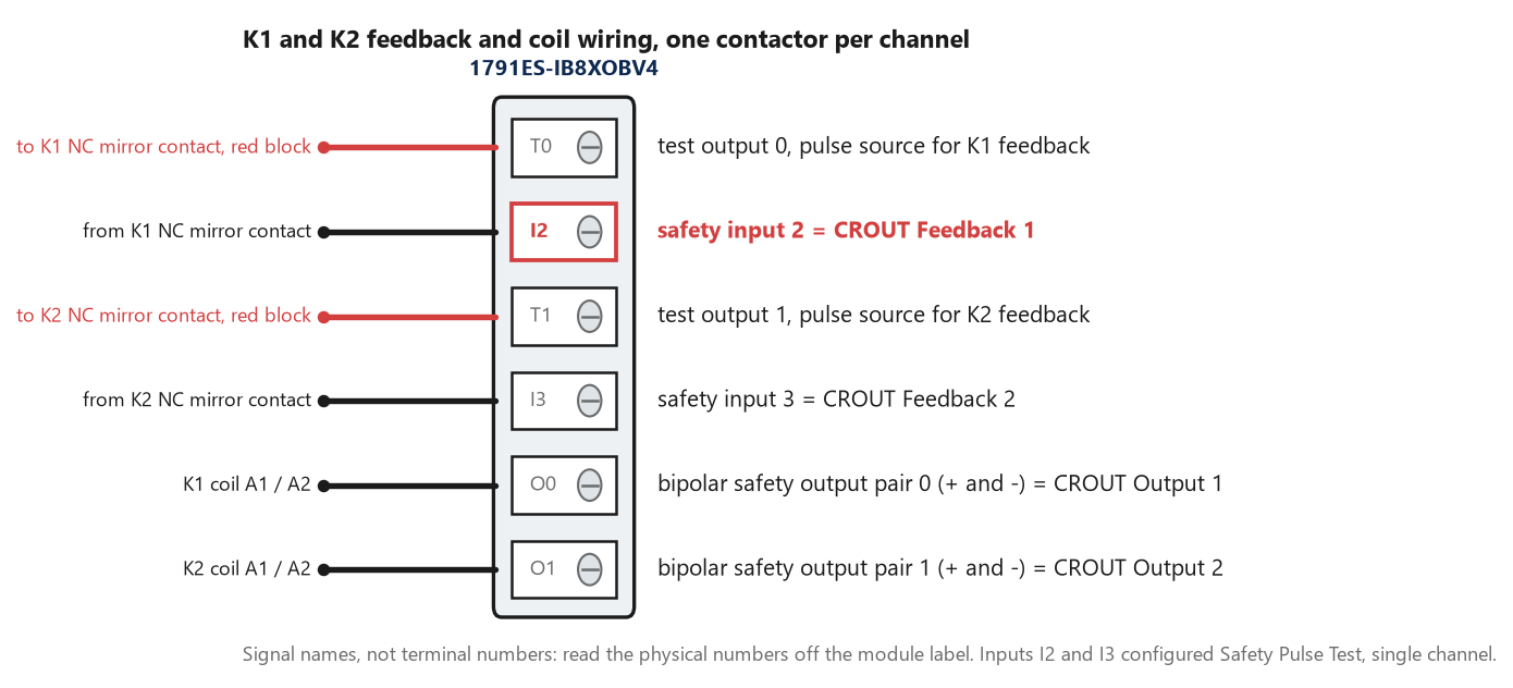
One feedback per channel, each from its own pulse-test source. Two NC contacts in series to one input is the relay wiring, and it is legitimate there because a 440R has only one feedback loop; on a CROUT it hides which contactor failed.
Configuring CROUT so it does not fault on the first reset
Two operands decide whether the instruction believes the contactors, and one of them is set wrong on most of the “faults on reset” calls. Feedback Type, in 1756-RM095, defines what the instruction expects the feedback to do: Positive means Feedback 1 ON when Output 1 is ON; Negative means Feedback 1 OFF when Output 1 is ON and ON when it is OFF. An NC mirror contact is closed with the contactor dropped out, so it is ON with the output OFF, and the type is Negative. Leave it at Positive with NC contacts and the instruction expects the feedback to be OFF at rest, sees it ON, and reports a feedback fault – 16#5003, both feedbacks ON unexpectedly, or 16#5006 on the first Actuate when they fail to turn ON, depending on which state it meets first after the download. Nobody has touched a contactor. The manual’s timing description of a feedback fault is precise about what clears it: the fault is cleared when the Reset input turns ON and both feedbacks correctly reflect the state of the outputs, so with the type wrong no number of reset presses will ever clear it, which is exactly the symptom.
Negative for NC contacts, and write it on the drawing next to the contactor.
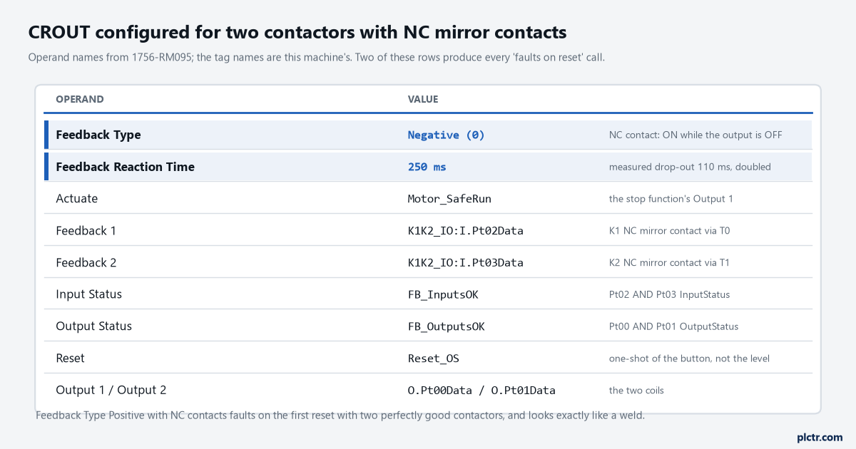
The two highlighted rows produce every “faults on reset” call. Input Status and Output Status are the module’s own status bits, and 1756-RM012 says to drive them above the instruction in the same routine.
Feedback Reaction Time is the second one. The range is 5 to 1000 ms and it is the time the instruction waits for each feedback to follow its output before faulting. The number to put in it is measured, not chosen: trend Output 1 against I2 at the safety task period, energise and de-energise the contactor twenty times, and read the longest gap. On this machine the K1 NC contact opened 38 ms after the output went true and closed 110 ms after it went false, the closing time being the longer one because the coil is 24 V DC with a diode across it, and the Safebook says why: a suppressor on a DC coil increases the drop-out time, and by an amount that depends on the suppressor. Two hundred and fifty milliseconds covers 110 with room for a cold panel. A thousand does not make anything safer; it makes a real weld take a second longer to report and a chattering feedback wire invisible.
Measure the drop-out with the suppressor fitted. It is the number the reaction time has to beat, and two more things belong in the same routine. Input Status and Output Status take the module’s own status bits for the feedback points and the output pairs, and 1756-RM012 says to drive those tags above the instruction so it reads the current scan’s status; an instruction whose status inputs are false does not run the outputs at all, and that is a different code, 16#20 or 16#21, not a feedback fault. And Actuate comes from the safety output of the stop function – the DCS or ESTOP instruction’s Output 1 – never from a standard tag on its own, because standard logic holding Actuate ON through a fault gives Diagnostic Code 16#5000, Actuate held ON, and the instruction will not restart until it drops.
Status above the instruction, Actuate from the stop function, reset as an edge.
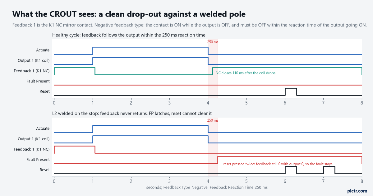
Top: the NC contact closes 110 ms after the coil drops, inside the window. Bottom: L2 welds on the stop, the NC contact never closes, FP latches at 250 ms, and the reset fails twice because feedback and output still disagree.
The same thing on a Siemens F-CPU, and on a relay
The FDBACK instruction in STEP 7 Safety is the CROUT with one feedback and one output. Its description in the SIMATIC Safety manual is short: Q goes to 1 when ON is 1, provided FEEDBACK is 1 and no feedback error is saved; Q goes to 0 when ON goes to 0 or a feedback error is detected; and a feedback error, ERROR, is set if the inverse of FEEDBACK does not follow Q within FDB_TIME. Inverse: the block already expects an NC contact, so there is no type to get wrong, and FDB_TIME is the same measured number as the reaction time. The error is saved, and with ACK_NEC at 1 it takes a rising edge at ACK to clear – the manual’s warning S033 says ACK_NEC may only be 0 if an automatic restart of the process is otherwise excluded, which is the same reset discipline as the Rockwell side: an edge, never a level. One input the Rockwell instruction does not have: QBAD_FIO, which takes the passivation status of the F-DQ channel driving the coil so that a passivated output is not reported as a feedback fault on top of everything else. Leave it unconnected and every channel fault produces two acknowledgements instead of one. On a 440R relay there is nothing to configure, and that is not the same as nothing to get wrong. The feedback loop is a pair of terminals, both contactors’ NC contacts and the monitored reset button are wired through it in series, and the relay checks the loop is closed before it will accept a reset – 440R-TD001 lists detecting faults in contactors as the first of the three things a monitoring safety relay is for. The thing to get wrong is the contact: a relay does not know whether the NC in its loop is a mirror contact or a snap-on block, and neither does a CROUT.
FDBACK has no type to get wrong; the relay has nothing to configure and still needs the right contact.
The thing everyone checks first
The contactor, every single time, and it is the last thing to check.
The call says the safety output faults on reset, and K1 gets swapped for the spare, and then K2, and the fault is still there because it was Feedback Type all along. So the order is the other way round. First, read the fault code and match it against the table: a code on both feedbacks at the first reset after a download is configuration; a code on one feedback that appeared once, on a machine that has run for a year, is a contact or a wire. Second, look at Feedback Type against the contact on the front of the contactor, NC or NO. Third, put the two feedback inputs in a trend with the outputs and press reset once, because the trend shows whether the NC contacts are closing at all, closing late, or bouncing, and each of those is a different fix. Only then pick up a contactor, and when you do, look for a pole that is discoloured on the load side.
Code first, then Feedback Type, then the trend, then the contactor.
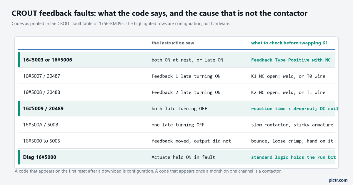
The codes are from the CROUT fault table in 1756-RM095. Three of the rows are configuration, and they are the three that get a contactor swapped for nothing.
Next step
Open the panel and read the front of K1 and K2: the mechanically linked or mirror contact symbol, the red block, the fixed cover. If the feedback is coming from a grey snap-on block, the EDM is reading a contact with no promise in it and the fix is a contactor, not a rung. Then trend the feedback against the output for twenty cycles with the coil suppressor fitted and write the drop-out time on the drawing next to the reaction time you set from it. The discrepancy time on the stop device’s two channels is the input-side version of the same measurement, worked through in discrepancy time on a dual-channel safety input, and whether this machine wants a CROUT at all or a 440R with one feedback loop is the question the relay-or-controller article exists to answer. The full E-stop and gate function that this output belongs to is wired end to end in the dual-channel interlock walkthrough.
The symbol on the front of the contactor comes first. Everything else follows from it.