On a Kinetix 5700 axis, .DN on a MAM means the move was accepted and .PC means the axis has arrived. Read the wrong bit and the next step of the sequence fires while a 2198-D032-ERS4 is still ramping the load down, which looks exactly like a tuning problem and is not one. This walkthrough takes one servo axis from a blank project to a running move: motion group, axis scaling, the enable and move instructions, homing, and the faults you will actually see. Hardware is a 1756-L83E with a Kinetix 5700 drive on CIP Motion, plus the S7-1500T equivalent for the Siemens side.
Everything below assumes the drive is already on the network with an IP address and the EDS installed.
What you need
| Item | Notes |
|---|---|
| Controller | 1756-L8xE or a 5069-L3xERM. The M suffix on CompactLogix is the motion licence, without it you get no axes |
| Drive | Kinetix 5700, for example a 2198-D032-ERS4 dual-axis inverter with a 2198-P070 DC bus supply |
| Motor | VPL or VPC rotary servo with a Hiperface DSL feedback cable. One cable carries power, one carries feedback |
| Software | Studio 5000 Logix Designer v33. Motion groups have been the same since v20 |
| Network | Managed switch with PTP passthrough and QoS. CIP Motion is time synchronised, an unmanaged switch will cost you sleep |
| Siemens option | S7-1500T CPU with TIA Portal v17, PROFINET IRT to a SINAMICS S210 |
Create the motion group and set the coarse update period
- Right-click Motion Groups in the Controller Organizer and choose New Motion Group. Name it
MG_Line. One group per controller is the normal case. - Open its properties and go to the Attribute tab. The Coarse Update Period is the heartbeat of every axis in the group.
- Start at 2 ms for a single axis, 4 ms once you pass six or eight CIP Motion axes on a 5580. Watch the controller task monitor after download and back off if the motion task is eating more than half the budget.
- The drive’s cyclic rate has to line up with the coarse update period. A group period the drive cannot serve gives you connection faults at power-up rather than an error at compile time.
The coarse update period is a periodic interrupt running above every task you wrote. Each time it fires, the planner recalculates position commands for all axes in the group. Setting it to 1 ms because faster sounds better is how a working line starts reporting task overlaps. What happens when a high-priority task steals the CPU is covered in PLC scan time and cycle time.
Add the axis and get the scaling right
- Add the drive under the Ethernet port with New Module, catalog 2198-D032-ERS4, and set its IP address.
- Right-click Motion Groups → MG_Line and add a New Axis of type AXIS_CIP_DRIVE. Name it
Ax_Infeed. - Open the axis properties and associate it with the drive and the drive’s axis channel on the General page.
- On Motor, pick the catalog number of the motor. The drive reads most of this from the motor’s feedback device, but the profile has to agree.
- On Scaling, this is where jobs go wrong. Set Position Units to something physical,
mmfor a linear axis orDegreesfor a rotary one. Then enter the transmission ratio so one motor revolution maps to real travel.
A ball screw example. A 10 mm lead screw driven through a 5:1 planetary gearbox moves the carriage 2 mm per motor revolution. Enter 5 motor revolutions to 1 load revolution, and 10 mm of travel per load revolution. Get this wrong and every move is out by the gearbox ratio, which on a 5:1 is obvious and on a 1.25:1 is subtle enough to survive commissioning.
Three more pages matter before you enable anything:
- Load, for the travel mode. Linear for a ball screw, rotary with unwind for a turntable or an indexer.
- Actions, for the soft travel limits and what the axis does on a fault.
- Planner, for maximum speed, acceleration, deceleration and jerk. These are ceilings, not what a move uses.
Enable, home and move
The instruction set is small. Learn six and you can run most machines.
| Instruction | What it does | Notes |
|---|---|---|
| MSO | Servo on | Drive energises, axis holds position. Fails if the drive is faulted |
| MSF | Servo off | Drops torque. The load falls unless there is a brake |
| MAH | Home | Active homing runs a move, passive homing only arms the marker latch |
| MAM | Move axis | Absolute or incremental, with its own speed, accel, decel and profile |
| MAJ | Jog | Runs until you stop it. Speed is changeable on the fly |
| MAS | Stop | Stops one process or all of them on that axis |
| MAFR | Fault reset | Clears axis faults. Does not clear the drive’s own hard faults |
A start-up sequence in structured text, one step per scan, with each instruction gated on the previous one finishing. The parameter order for MAM below is Axis, MotionControl, MoveType, Position, Speed, then the accel, decel and profile fields; build it once with the instruction’s fill-in-the-blank editor in Studio 5000 and treat this as the pattern, not a line to retype from a screen, because the trailing optional fields vary with firmware:
(* Ax_Infeed start-up. Studio 5000 v33, ST in a 10 ms periodic task *)

CASE Seq.Step OF

  0:  (* wait for a healthy, un-faulted axis *)
      IF Ax_Infeed.AxisFault = 0 AND Start_PB THEN
          MAFR(Ax_Infeed, MI_Reset);
          Seq.Step := 10;
      END_IF;

  10: (* servo on *)
      MSO(Ax_Infeed, MI_ServoOn);
      IF Ax_Infeed.ServoActionStatus THEN
          Seq.Step := 20;
      END_IF;

  20: (* home once per power cycle, skip if absolute feedback *)
      IF Ax_Infeed.AxisHomedStatus THEN
          Seq.Step := 30;
      ELSE
          MAH(Ax_Infeed, MI_Home);
          IF MI_Home.PC THEN Seq.Step := 30; END_IF;
      END_IF;

  30: (* absolute move to the load station, MoveType 0 = Absolute *)
      MAM(Ax_Infeed, MI_Move, 0, Pos_Load, Spd_Load, 0, Accel_Rate, 0, Decel_Rate, 0);
      IF MI_Move.PC THEN Seq.Step := 40; END_IF;

  40: (* index 90 degrees, incremental, MoveType 1, over and over *)
      MAM(Ax_Infeed, MI_Index, 1, 90.0, Spd_Index, 0, Accel_Rate, 0, Decel_Rate, 0);
      IF MI_Index.PC THEN Seq.Step := 40; END_IF;

END_CASE;
Each motion instruction needs its own MOTION_INSTRUCTION tag. Sharing one tag between MSO and MAM is the classic beginner mistake, and the symptom is a move that reports done before it moved. Watch .DN for accepted, .PC
.ER with .ERR when the instruction is rejected.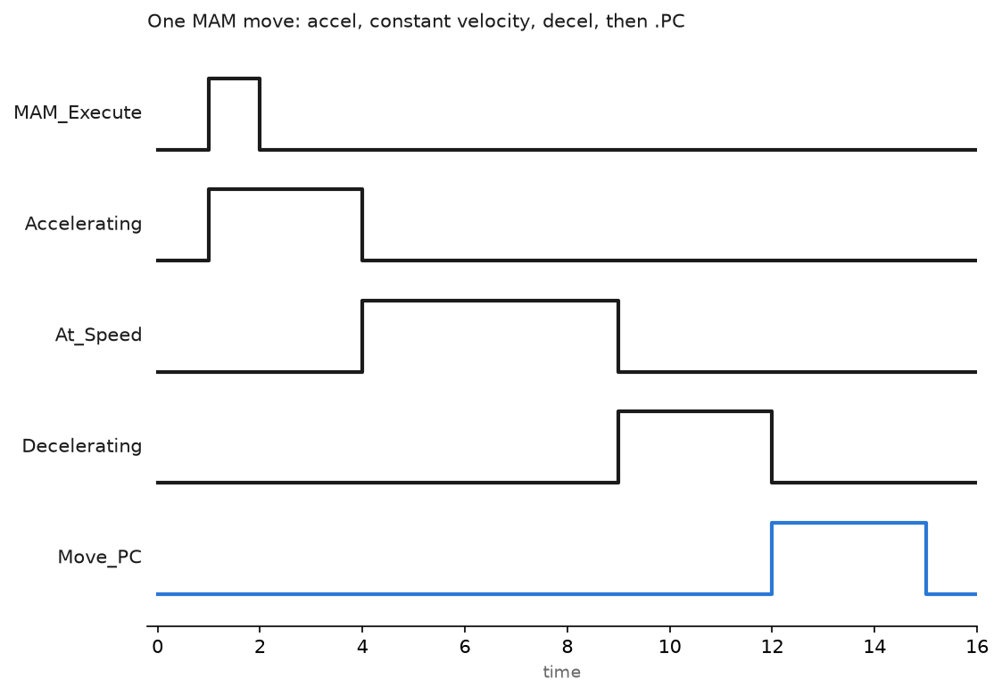
That is the shape of every trapezoidal move. Accel until commanded speed, constant velocity, decel into the target, then .PC once the axis is inside its position tolerance. On a short move the constant velocity section disappears and the profile becomes triangular.
Home the axis without guessing
Homing mode lives on the axis Homing page, not in the MAH instruction.
- Active homing with a switch and marker suits incremental feedback. The axis jogs at home speed until the limit switch trips, creeps back until the encoder marker, and takes the home offset as its position. Repeatable to one marker spacing, so gear it so one motor revolution is smaller than the switch hysteresis.
- Passive homing moves nothing. It arms the marker latch and waits for the machine to be moved by a hand wheel or another axis.
- Absolute feedback needs no homing move. A multi-turn absolute encoder holds position through a power cycle. Check the battery or capacitor state before you trust it after a long shutdown.
If marker pulses are new territory, what is an encoder, usage areas and types covers incremental against absolute feedback.
Gear and cam when two axes must agree
MAG gears a follower to a master at a fixed ratio, for a draw roll following a line shaft. The ratio is changeable while running, and a gear clutch ramps the follower up over a distance instead of a step change.
MAPC runs a position cam, a table of master position to follower position rather than a fixed ratio. Build the profile as an array of CAM points, compile it once with MCCP into a CAM_PROFILE array, then execute MAPC against the compiled profile. Linear segments are cheap and jerky; cubic segments cost more planner time and give continuous velocity across the point, which is what a flying shear needs. Compile the profile at first scan, not every cycle, because MCCP is expensive.
The Siemens equivalent on an S7-1500T
Same ideas, different names. In TIA Portal you add a technology object rather than an axis tag.
| Logix | S7-1500T | Notes |
|---|---|---|
| AXIS_CIP_DRIVE | TO_PositioningAxis | TO_SynchronousAxis when the axis will be geared or cammed |
| MSO / MSF | MC_Power | Enable input, Status output, held true while the axis runs |
| MAH | MC_Home | Mode input selects active, passive or direct homing |
| MAM | MC_MoveAbsolute, MC_MoveRelative | Done, Busy, CommandAborted, Error per PLCopen |
| MAJ | MC_MoveJog | |
| MAG | MC_GearIn, MC_GearInPos | |
| MAPC | MC_CamIn with a TO_Cam | |
| MAS | MC_Halt, MC_Stop |
The PLCopen state machine is stricter than Logix: a block call whose Execute drops before Done sets leaves a lost completion edge, so latch the result. Use PROFIdrive telegram 105 for dynamic servo control, which moves the position loop into the drive and needs IRT rather than plain PROFINET RT, the same trade-off covered in EtherCAT in high-performance PLC systems.
Field notes: what actually goes wrong
Excessive position error on a gantry. A two-axis pick and place faulted on the Y axis every third cycle, always during decel at high speed. Velocity feedforward was left at 0, so the loop chased the profile on proportional gain alone and trailed by more than the error tolerance. Setting feedforward near 100 percent and rerunning the autotune cut following error by an order of magnitude. Raising the tolerance instead would have hidden a real problem.
Conversion set for the motor, not the load. A packaging infeed was commissioned with the gearbox ratio left at 1:1 because the mechanical drawing arrived late. Every 100 mm index moved 500 mm. Nothing broke only because the soft travel limit tripped. Set the soft limits before the first MSO, every time.
Coarse update period at 1 ms with fourteen axes. A retrofit added six axes to an existing eight-axis group and nobody revisited the group period. The line ran, then started logging task overlaps on the continuous task and the HMI went sluggish under load. Moving the group to 4 ms fixed both, with no measurable change in motion quality.
Frequently asked questions
Why does my MAM report .PC before the axis has stopped?
Either two instructions share one MOTION_INSTRUCTION tag, or you are reading .DN and thinking it means finished. .DN means the move was accepted, .PC means it is complete.
Do I need a separate motion licence on CompactLogix?
You need a controller with the M suffix, for example 5069-L320ERM. Integrated motion is not a software option you add later to a non-M controller.
Can I run CIP Motion through a plain unmanaged switch?
It often appears to work on a small system, then fails intermittently. CIP Motion needs PTP and traffic prioritisation, so use a managed switch with QoS and keep motion off the business VLAN.
How do I read which fault the axis has?
Ax_Infeed.AxisFault is a bit-mapped word for controller-side faults. For drive-side detail, GSV the AXIS object or open the drive properties online, where Studio 5000 decodes the drive fault text.
What is the difference between gearing and camming?
Gearing holds a constant ratio between master and follower. Camming follows an arbitrary curve defined as a table. Use MAG when the follower profile is one multiplier, MAPC when it has dwell, reverse or a shaped return.
Next step
Package the enable, home and move sequence above into a reusable block before you copy it to the second axis. The pattern is in Studio 5000 Add-On Instructions. If part of the machine runs on a VFD rather than a servo, how to add a PowerFlex AC drive to a Studio 5000 project covers that side of the same line. For a machine where every section follows a line-speed reference times a draw ratio instead of a position, see textile warper and stenter control.