A PowerMonitor 1000 puts L1 current in input registers 30201 and 30202, as one IEEE 754 float with the high word in 30201, and answers function code 04 for it. Those four facts — which register, how many, which order, which function code — are the whole job of getting a Modbus RTU power meter into a PLC, and every one of them comes from the meter’s manual, not the PLC’s.
The PLC side is short once you have those four in hand.
On an S7-1200 it is one Modbus_Comm_Load in the startup OB and one Modbus_Master in the cycle OB with MODE 0, DATA_ADDR 30201 and DATA_LEN 32. On a Micro800 it is the serial port set to Modbus RTU master and a MSG_MODBUS. What takes the afternoon is the wiring, the address offset, the word order and reading a STATUS of 16#80C8 correctly, so that is where most of this goes.
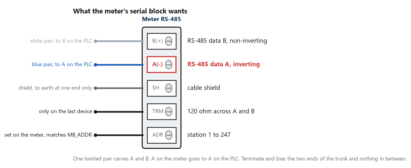
A on the meter goes to A on the PLC. That sounds too obvious to write down, and crossed A and B is still the most common reason the first request times out.
Four things the Modbus RTU power meter manual has to tell you
Function codes first. The PowerMonitor 1000 manual lists what it answers: 03 Read Holding Registers, 04 Read Input Registers, 06 Write Single Holding Register, 16 Write Multiple Holding Registers and 08 Diagnostics. It says in the same paragraph that the meter does not initiate Modbus commands and only responds to a master, which is true of every meter and is why the PLC must be the master. A meter that publishes its readings in the 30000 range wants 04; one that puts them in the 40000 range wants 03. Send 03 to a 30000-range table and the meter answers with exception 01, function not supported, which the S7-1200 reports as STATUS 16#8381. The register map second, and the offset that comes with it. The manual says the meter supports input registers, read-only, with addresses in the 30000 range, and holding registers, read-write, in the 40000 range. L1 current is 30201-30202. On the wire, function code 04 carries a zero-based address, so 30201 goes out as 200; the S7-1200 hides that from you, because Modbus_Master takes the 30201-style number directly and picks the function code from the range, and the Micro800 does the same with six-digit addresses, 300201. What neither can hide is a meter manual that prints the zero-based number and calls it an address. If the map says “register 200” and you type 30201, you are one register out, the float lands across the wrong pair, and you read garbage that looks plausible. Exception 02, data address error, 16#8383 on the S7, is the one you get when the offset pushes you past the end of the table; when it does not, you get no error at all.
Data type third. The manual states that input and holding registers are 16 bits, that floating-point values are represented as big-endian two-register arrays in IEEE 754 format, and it gives the example 40101-2, where 40101 holds the most significant bytes. That is the sentence to find in whatever meter you have, because a meter that sends the low word first is common, the S7-1200 will not warn you, and the symptom is a voltage reading of 2.4e-41. Serial parameters last. This meter’s RS-485 port defaults to 38.4k baud, 8 data bits, 1 stop bit, no parity, station address 1 to 247, with the protocol selectable between DF1 and Modbus RTU slave. Read those off the meter’s own display before you configure anything, because the default on the meter and the default on the PLC port are rarely the same number.
What actually gets wired
Two wires and a shield. RS-485 is one twisted pair carrying A and B, with a shield earthed at one end. On the CM 1241’s 9-pin connector the S7-1200 manual puts B, TxD/RxD+, on pin 3 and A, TxD/RxD-, on pin 8; meters label the same pair every way there is, D+ and D-, plus and minus, or A and B with the polarity reversed, so match the signal names, not the letters. The S7-1200 manual’s rule for the ends of the segment is a single sentence: you terminate and bias only the two ends of the RS-485 network, and the devices in between are not terminated or biased. The Siemens network connector has a switch for it; the CB 1241 does it with internal resistors you link in at the terminals. A meter at the far end of a trunk usually has a termination jumper or a switch of its own. Bias matters more than people think. Without it the line floats between messages, and a floating pair is where the CRC errors come from — 16#8380, noise on an otherwise correct message. Termination at both ends and bias at one is the ordinary arrangement; three terminators on a short line is the ordinary mistake. A segment carries at most 32 devices on the RS-485 drive capability, the manual says, and Modbus addressing allows 247 slaves, which is why anything past 32 needs a third-party repeater. One meter on a 30 m run needs none of that, and it still needs the two ends done properly.
The S7-1200 side
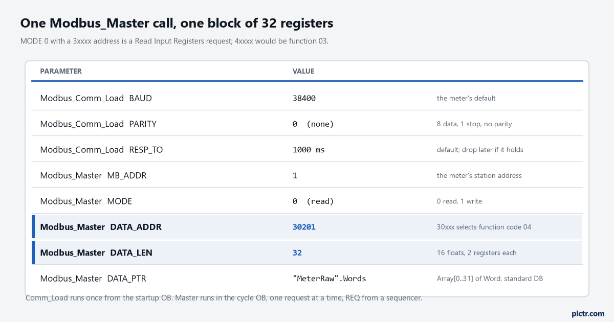
The two highlighted values do the work. 30201 selects function code 04 by its range, and 32 registers is the whole volts, amps and frequency table in one request.
Modbus_Comm_Load runs once. The manual says to call it from a startup OB and execute it one time, and to run it again only when a parameter changes; each port gets one instance DB, and that DB is what you hand to the MB_DB pin. BAUD takes the listed rates from 300 to 115200, PARITY is 0 for none, 1 odd, 2 even, and RESP_TO is the time the master waits for a reply before retrying — 1000 ms by default, which is long, and the right value until the link is proven. One thing bites people who put their configuration in a distributed rack: the manual notes that after a power interruption or a module pull on PROFINET or PROFIBUS I/O the hardware configuration is reloaded and Modbus_Comm_Load has to run again, which is the reason that “run it once” turns into “run it once, and again whenever the rack comes back”. Modbus_Master does the reading. The parameters are MB_ADDR, the station address; MODE, where 0 is read and 1 is write; DATA_ADDR, the starting Modbus address in the slave’s own numbering; DATA_LEN, in words for register reads; and DATA_PTR, a pointer to the M or DB area the words land in. The manual’s function table maps the combinations: MODE 0 with an address in 30001 to 39999 is function 04, 0 with 40001 to 49999 is function 03, 1 with a 4xxxx address and a length of 1 is function 06, and length 2 or more is function 16. Up to 125 words per request. DATA_PTR has a rule that costs an hour if you miss it. The manual says the data block must allow direct addressing, meaning the Standard access attribute; from instruction version V4.0 you may use an optimized DB, but only for a single element or an array of elementary types. An Array[0..31] of Word in a standard DB works everywhere. A Struct of named Reals in an optimized DB does not, and the error is 16#818C, invalid pointer, which reads like a typing mistake.
Then the rules the manual sets for calling it, because they are the difference between a link that runs for years and one that hangs on Thursdays. One Modbus_Master instance DB per port, shared by every call on that port. All calls from the program cycle OB and never from a cyclic interrupt as well. One request active at a time: once a request starts, that instance has to be executed every scan with EN
DONE or ERROR, and any other call with REQ set in the meantime gets an error. So a meter with a volts table at 30201 and a power table at 30301 gets two calls, sequenced, the second REQ raised in the scan after the first returns. DONE and ERROR are true for one scan, and STATUS is valid only in that scan; copy it to a Static when ERROR is true, or you will be looking at zero. Once the words are in the DB, the float is two of them. With the meter sending high word first, an Array[0..31] of Word viewed as sixteen Reals through a second DB layout, or a MOVE of two words into a DWord and a DWORD_TO_REAL reinterpret, gives the number directly. With a low-word-first meter, swap the words before the reinterpret. Do it once in a small FC and give it a name, because the next meter will need the other order.The Micro800 side, briefly
The Micro800 manual states its serial port drivers, and Modbus RTU is one of them, with Master, Slave and Auto as the role, 19200 baud and no parity as the defaults, and a response timer of 200 ms. It uses six-digit addressing by default — input registers 300001 to 365536, holding registers 400001 to 465536 — and accepts five-digit numbers as the older style. The manual is direct about byte order: Modbus is big-endian, Micro800 controllers are big-endian, so nothing is reversed, and a REAL takes two consecutive registers with the most significant first. Which lines up with the PowerMonitor and with most meters, and not with all of them. The read itself is MSG_MODBUS, and the performance note in the appendix tells you why the meter read belongs on a slow cadence: messages are serviced when the instruction executes, so at a 100 ms scan a port carries at most ten requests a second, and a request-response protocol with a meter’s turnaround on the end of it delivers less.
On a ControlLogix or CompactLogix there is no native Modbus RTU; that is a gateway or a serial module with its own configuration, and it is a different article.
Reading the register map like a meter does
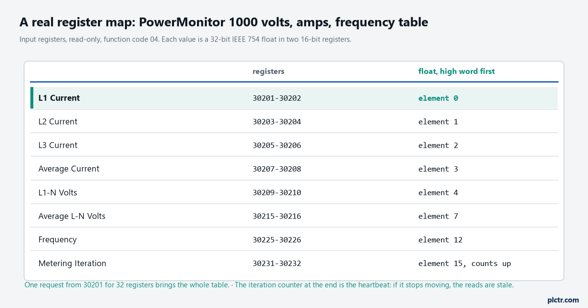
Sixteen floats in thirty-two consecutive registers, which is why one request for 32 words from 30201 is the right shape. The last element counts up on every metering pass.
The table the meter publishes for volts, amps and frequency runs from 30201 to 30232: currents at 30201 to 30208, line-to-neutral volts from 30209, line-to-line from 30217, frequency at 30225-30226, then unbalance and, at 30231-30232, a metering iteration that increments on every new calculation. The power table starts at 30301.
Read the whole block in one request and pull the values out by offset.
One request per value is the other way, and sixteen requests at 38.4k on a 200 ms turnaround is three seconds for a set of numbers the meter produced together.
That iteration counter is worth more than it looks. Copy it every read and compare it to the last one. If the reads are succeeding and the counter has stopped, the meter is answering from a frozen table — a meter with its CT inputs open or a firmware fault will do that — and nothing in Modbus_Master will tell you. It is the same trick as reading a heartbeat through a PUT/GET link.
A good response proves the link and says nothing about the data.
The word order, and the number that gives it away
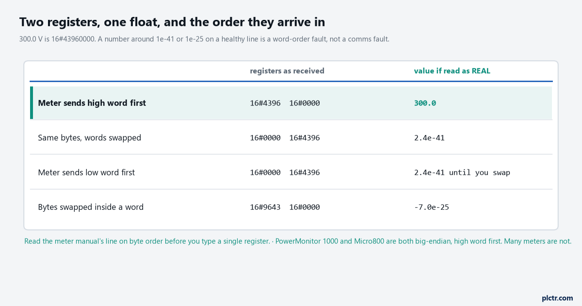
The same four bytes. 300.0 V read in the wrong order is 2.4e-41, and a byte swap inside the word gives -1.6e-25. Neither is a comms fault, and both arrive with DONE true.
300.0 as a float is 16#43960000. A meter that sends the high word first delivers 16#4396 then 16#0000, and a Real overlaid on the pair reads 300.0. Swap the words and the same bytes are 16#00004396, which is 2.4e-41, a denormal number that shows up on a watch table as “0.0” if the display rounds and as a string of noise if it does not. Reverse the bytes inside each word instead and you get -1.6e-25. Both come with DONE true, STATUS 0 and no error anywhere, because the transfer was perfect and only the interpretation is wrong.
So the check is on the value, not on the status word.
Read line-to-neutral volts first, because you know what it should be within ten percent. If it is a sane number, the order is right for every other float in the same table. If it is 1e-41 or 1e-25 or 3e+38, swap and read again, and write the order into the DB comment for whoever inherits it.
When STATUS comes back non-zero
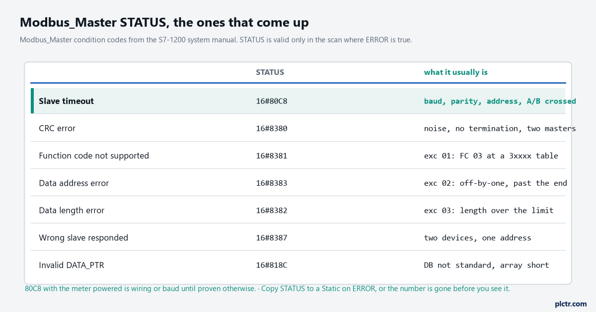
The manual’s condition codes, sorted by how often they are the answer. 80C8 with a powered meter is wiring, baud or address; a CRC error on a short line is termination.
The S7-1200 manual’s own wording for 16#80C8 is the best troubleshooting note in the chapter: slave timeout, the specified slave did not respond in the specified time, check the baud rate, parity and wiring of the slave device, and the error is only reported after the configured retries.
Baud, parity, address, then A and B, in that order, and check them on the meter’s display rather than in the drawing.
The 83xx codes carry the meter’s exception in them. 16#8381 is exception 01, function code not supported, which is a 03 sent for a 04 table or the other way round. 16#8383 is exception 02, data address error, and the manual adds “or address outside the valid range of the DATA_PTR area”, which is the off-by-one or a DATA_LEN that runs past the table. 16#8382 is a data length error and 16#8384 a data value error. 16#8387 is the one that finds a wiring fault: wrong slave responded, which means two devices share an address, and the manual’s list of things the master checks is why Modbus survives on a network that nobody has documented. The dead end is RESP_TO. When the first read times out the reflex is to make the timeout longer, and a meter that does not answer in 1000 ms is not going to answer in 5000. Lengthening it only makes each retry slower. Leave it at the default until the link works and shorten it afterwards, so a meter that goes away is noticed in a second rather than in five.
What to check first
On the meter’s display: protocol, baud, parity, address. On the PLC: the same four in Modbus_Comm_Load and MB_ADDR, then a single Modbus_Master reading two registers of line-to-neutral volts, DATA_PTR on a standard DB, STATUS copied to a Static. When that reads a believable voltage, and only then, widen the request to the whole table and add the sequencer for the second one. The physical side of the link, the shield and the two ends of the trunk, is the same argument as the RS-485 segment rules for PROFIBUS at a lower baud, and the wider question of which protocol to put a meter on at all is in PLC energy management.