PROFIBUS segment length is the first number to check when stations start dropping out after somebody extended a run. It is not one number. It moves with the transmission rate set in the master, and the fall is steep: the cable that carries 1200 m at 93.75 kbit/s carries 200 m at 1.5 Mbit/s. Below is the full table for type A cable, where a repeater helps, what termination has to look like, and the meter checks that separate a length problem from a wiring problem.
Examples come from an S7-300 with a CPU 315-2 DP, ET 200M stations and MICROMASTER 440 drives. The limits belong to the physical layer, not to any one master.
What you need
| Item | Notes |
|---|---|
| Type A bus cable | Siemens FC standard cable 6XV1830-0EH10 is type A. Check the jacket print on every section |
| Bus connectors | Any RS 485 connector with a switchable terminator. Order it for the angle the panel needs and with a PG socket only where you want to plug a laptop in |
| Repeater | RS 485 repeater 6ES7972-0AA02-0XA0, or a diagnostic repeater if you also want fault location |
| Multimeter | Enough for the resistance checks below. A PROFIBUS tester is better if the site has one |
| STEP 7 or TIA Portal | To read and change the transmission rate on the DP master system |
| Route length | The measured length of the cable, not the drum count |
The table: how far you can go at each rate
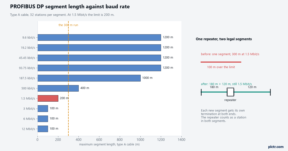
Segment length is defined per segment on type A cable, with up to 32 stations in that segment.
| Transmission rate | Type A cable | Type B cable |
|---|---|---|
| 9.6 kbit/s | 1200 m | 1200 m |
| 19.2 kbit/s | 1200 m | 1200 m |
| 45.45 kbit/s | 1200 m | 1200 m |
| 93.75 kbit/s | 1200 m | 1200 m |
| 187.5 kbit/s | 1000 m | 600 m |
| 500 kbit/s | 400 m | 200 m |
| 1.5 Mbit/s | 200 m | not specified |
| 3 Mbit/s | 100 m | not specified |
| 6 Mbit/s | 100 m | not specified |
| 12 Mbit/s | 100 m | not specified |
Type A is the only cable worth installing: 135 to 165 ohm impedance between 3 and 20 MHz, below 30 pF/m capacitance, 110 ohm/km loop resistance, a 0.64 mm conductor, 0.34 mm² in cross-section. Every number in the type A column comes from that specification.
Type B is the older, looser class, and the column shows what it costs above 187.5 kbit/s. Those figures come from the earlier EN 50170 classification and are worth checking against the current PI cabling guideline if you are ever asked to design around them. If the cable in the tray is neither, the table does not apply and you read the manufacturer’s data instead. Festoon and drag chain cables often carry their own, shorter figures at the higher rates.
Why the limit shrinks as the rate goes up
Nothing about the cable changes when you change the rate. What changes is how much time the receiver has.
At 9.6 kbit/s one bit lasts about 104 microseconds. At 1.5 Mbit/s it lasts 0.67 microseconds, at 12 Mbit/s about 83 nanoseconds. Propagation in type A cable is roughly 5 nanoseconds per metre, so 200 m puts a full microsecond of travel between the two ends. Attenuation rounds off every bit edge, and a reflection from a bad joint or a missing terminator arrives late.
At 93.75 kbit/s all of that lands harmlessly inside a bit ten microseconds long. At 1.5 Mbit/s the rounding and the echo arrive while the receiver is still sampling. The stations furthest from the master suffer first, because they see the most attenuated signal and the longest round trip.
Count the segment properly before you blame the cable
A segment is the run between two terminators. Three things get counted wrong on site.
- Station count. Up to 32 stations per segment, and the master counts. A repeater counts as a station in each segment it joins.
- Route length. Drum figures and tray figures disagree, usually by ten to twenty per cent, because of service loops and panel slack. Measure before deciding anything from the table.
- Addresses. Addresses 0 to 125 are usable, 126 is the factory commissioning address, 127 is broadcast. A network built from several segments can hold up to 126 stations, and each segment still has its own 32 station limit.
Spurs are the fourth trap. At 1.5 Mbit/s and above, run the cable into the connector and out again at every station and use no stubs. Below that the guideline allows a limited total stub length per segment, shrinking as the rate rises. If a station needs a drop, use a repeater and make that drop a segment of its own.
Two fixes that work, and the ones that do not
Lower the transmission rate. In HW Config, open the properties of the DP master system, go to Network Settings, change the transmission rate and download. Every DP slave detects the rate on its own, so no slave needs touching. Moving from 1.5 Mbit/s to 500 kbit/s buys 400 m and roughly triples the time the same data spends on the wire. Before you commit, read the calculated bus cycle time in the bus parameters dialog at both rates. On eleven stations with a few bytes each it will not matter. On a filler with a drive that needs a setpoint every cycle, it might.
Add a repeater. One repeater turns an over-length segment into two legal ones and the network keeps its rate. The rules that get missed:
- Each new segment needs a terminator at both of its ends. The repeater provides one of them, with a switch on its housing.
- The repeater counts against the 32 station limit in both segments.
- A plain RS 485 repeater takes no bus address. A diagnostic repeater is a DP slave and does take one.
- Repeaters add delay, which changes the bus timing the master calculates. The bus parameters dialog in the master’s network settings has a field for the number of repeaters in the longest signal path. Set it, do not leave it at zero.
- The repeater manual states the maximum allowed in one signal path. For the Siemens RS 485 repeater that figure is nine. It differs by product, so read the manual.
What does not work: swapping connectors one at a time until the fault moves, and adding a third terminator mid-run to help the signal. The second habit turns a marginal segment into a dead one.
Termination, bias, and the station that gets switched off
The terminator at each end of a segment is three resistors, not one: 220 ohm across A and B, 390 ohm from B up to VP at 5 V, and 390 ohm from A down to data ground. The 220 ohm kills reflections. The two 390 ohm resistors hold the line at a defined level when nobody is transmitting, and without them the receivers see noise between telegrams.
That bias comes from the 5 V supply in the connector, which comes from the station it is plugged into. A terminating station switched off leaves the segment with a terminator but no bias, and the symptoms look exactly like a cable fault. If the last station sits in a panel that gets isolated for maintenance, move the termination to a repeater or an active terminator with its own supply.
On the 9 pin connector, pin 3 is the B line with the red core, pin 8 the A line with the green core. A single crossed pair mid-run passes a continuity test and still ruins a high rate segment.
Ten minutes with a meter
Do this with the bus powered down, unless the step says otherwise.
- Both end terminators on, everything else off: measure A to B. Expect about 110 ohm, the two 220 ohm resistors in parallel. Near 220 ohm means only one terminator is active. About 73 ohm means a third one is switched on somewhere.
- Both terminators off: measure A to B again. It should read open. A low reading is a pinched cable or a shorted connector.
- Measure A to shield and B to shield. Both open.
- Check the shield is clamped over 360 degrees to PE at both ends of every section, not pigtailed to a terminal.
- Power up and measure DC between A and B at the far station with the bus idle. You want a steady offset, not zero. Zero means the bias is missing, which takes you back to the terminating station and its supply.
- Walk the run and count terminators. Two per segment, at the physical ends, no others.
The same discipline applies on Ethernet based networks: different failure modes, same habit of measuring before replacing. More in PLC networking that survives a busy plant floor and PLC communication protocols for SCADA.
What we see in the field
The run that worked for twelve years at exactly the limit. A 200 m segment at 1.5 Mbit/s is legal and will run for a decade on good connectors, a proper shield bond and no stubs. That margin was also hiding two mediocre joints. Add 100 m and the margin is gone, the joints start to matter, and the fault looks new when the weakness dates from commissioning.
The far station that was really a spur. A drive added at 1.5 Mbit/s with a 6 m drop to a local panel. Six metres of unterminated stub reflected enough to knock out the two stations after it, and nobody counted it as length because it was not part of the trunk. On a bus carrying drives, see also PLC motor control and drive systems.
Frequently asked
Can I run different baud rates on one PROFIBUS network? No. One rate applies to the whole DP network. Slaves detect it automatically, which is why a rate change needs only a master download.
Does a repeater need a PROFIBUS address? A plain RS 485 repeater does not. A diagnostic repeater is a DP slave with its own address and diagnostic data, worth the money on a long bus with intermittent faults.
Does fibre remove the length limit? It removes the copper limit on that leg only. Reach then depends on the fibre and the link module: tens of metres on plastic fibre, a few hundred on PCF, kilometres on glass. The copper segments at each end still obey the table.
Next step
Measure the run, set the rate the length allows, and write both numbers on the panel drawing so the next extension starts from a fact. If the bus stays unstable once the length is legal, the fault is joints, shields or spurs: the sequence is in advanced troubleshooting techniques for PLC systems.