Most of a PLC motor control VFD project is settled in the first hour by three decisions: contactor or drive, hardwired or network control, and who owns the stop circuit. Get those right and the programming is an afternoon. Get them wrong and you are back in the panel with a drill. This walkthrough covers a direct on line starter, a PowerFlex 525 on EtherNet/IP, and a SINAMICS G120 on PROFINET with telegram 1.
The kit in this example
| Item | Detail |
|---|---|
| Controller | 1756-L83E, Studio 5000 v33 |
| Drive | PowerFlex 525, 7.5 kW, embedded EtherNet/IP |
| Motor | 7.5 kW, 400V, 14.6 A full load, 1460 rpm |
| Starter comparison | Contactor plus thermal overload relay, class 10 |
| Siemens side | S7-1500 with a G120 CU240E-2 PN, telegram 1 |
| Safety | Hardwired category 3 stop into STO on the drive |
Decide between a starter and a drive on the load, not the budget
| DOL starter | VFD | |
|---|---|---|
| Starting current | 6 to 8 times full load | Under full load current |
| Speed | One | Anything from creep to above base speed |
| Soft stop | No, coast or plug | Controlled ramp |
| Cable and EMC | Ordinary cable | Shielded cable, gland at both ends, grounding matters |
| Cost per motor | Low | Higher, plus panel heat and space |
| Good for | Pumps that run all shift, small fans, hydraulic packs | Conveyors, anything that has to match another axis, anything where you want to cut energy |
A 7.5 kW pump that starts twice a day does not need a drive. A conveyor that has to track the machine downstream does, and the moment you put a drive on it you inherit cable screening, reflected wave on long runs, and a new set of fault codes to learn.
Wire the stop so it works when the PLC does not
The seal-in rung is still the heart of a starter circuit, but it must not be the only thing stopping the motor. The stop button and the emergency stop belong in the control circuit or in the safety relay, wired normally closed. The PLC bit is how the operator asks for a stop. The wiring is what guarantees it.
Rung 0: run command with seal-in
  ---] [---------]/[--------] [---------( )---
    Start        Stop      Drive_Ready   Run_Cmd
   |
   ---] [---
    Run_Cmd

Rung 1: drive fault latch
  ---] [--------------------------------( )---
   Drive_Faulted                      Drive_Alarm
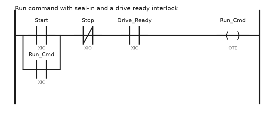
Drive_Ready in series is the part people leave out. Without it the PLC keeps commanding run into a faulted drive, the operator sees a green lamp, and nothing turns. The same rung with a timer on the start is in motor start and stop via timer, and the classic RSLogix version is in RSLogix motor start stop program.
On a line-fed starter you still need the thermal overload relay. The drive protects the motor it is driving, and nothing else.
Set up the PowerFlex 525 before you write a rung
- Power the drive, press the keypad Esc to the parameter list and work through the motor nameplate group: motor volts, hertz, overload current, full load amps, poles and rated rpm. Copy them from the plate on the motor, not from the order.
- Set the accel and decel times. P041 and P042 are the first pair. Start at 10 seconds each and shorten them once the load is known.
- Point the drive at the network for start and reference. The start source and speed reference parameters both have to select the embedded EtherNet/IP port, otherwise the drive accepts your command and takes its speed from the keypad.
- Set the IP address in the C128 group, either static or from BOOTP. Static, always, on a machine.
- In Studio 5000, add the drive under the Ethernet port with its Add-On Profile. Set the RPI to 20 ms. The profile creates the command and status tags for you, which is much better than counting bits in a raw assembly.
- Decide what the drive does when the network stops. The comm loss action must be fault and stop for anything that moves a load.
The full add sequence with the dialog boxes is in how to add a PowerFlex AC drive to a Studio 5000 project.
Once the profile is in, the logic is short:
(* Speed reference in Hz, scaled from the HMI 0 to 100 percent *)
Drive1_SpeedRef_Hz := (HMI_Speed_Pct * 50.0) / 100.0;

Drive1:O.Start   := Run_Cmd AND Drive1:I.Ready;
Drive1:O.Stop    := NOT Run_Cmd;
Drive1:O.ClearFaults := HMI_Reset_PB;

(* Feedback the operator actually needs *)
Drive_At_Speed  := Drive1:I.AtSpeed;
Drive_Output_Hz := Drive1:I.OutputFreq;
Drive_Faulted   := Drive1:I.Faulted;
Tag names come from the profile version, so check them in the tag browser rather than typing from memory.
The same motor on a G120 with telegram 1
Telegram 1 is two words out and two words back. The control word STW1 carries the commands, NSOLL_A carries the speed setpoint as a scaled integer where 16384 equals 100 percent of the reference frequency. Coming back you get ZSW1 and the actual speed in the same scaling.
The sequence that trips people up is the enable order. You send 16#047E to get the drive ready, then 16#047F to run. Send 047F from a standing start and the drive sits there while you check cables.
// S7-1500, telegram 1 on a G120
IF NOT Run_Cmd THEN
    "Drive_STW1" := W#16#047E;          // ready to run, no start
ELSIF "Drive_ZSW1".%X0 THEN             // ready to switch on
    "Drive_STW1" := W#16#047F;          // run
END_IF;

// 50 Hz reference = 16384
"Drive_NSOLL" := REAL_TO_INT(HMI_Speed_Pct * 163.84);

"Drive_Running"   := "Drive_ZSW1".%X2;
"Drive_Fault"     := "Drive_ZSW1".%X3;
A worked Siemens start and stop on a drive, with the hardware configuration around it, is in Siemens PLC drive motor start stop.
Read the fault before you reset it
| Code on a PowerFlex 525 | Meaning | Where to look |
|---|---|---|
| F004 | Undervoltage | Supply dip, loose incomer, or a contactor dropping out |
| F005 | Overvoltage | Decel too fast into an overhauling load, no brake resistor |
| F007 | Motor overload | Motor nameplate parameters wrong, or the load really is too heavy |
| F012 | Hardware overcurrent | Short on the output, or accel far too fast |
| F013 | Ground fault | Motor winding or cable to earth, meg it before resetting |
| F081 | Comm loss | Network, not the motor |
Resetting a drive without reading the code is how the same fault comes back on the night shift. Log the code into the PLC and timestamp it, because the drive keeps only a short fault queue.
Field notes
Decel time that kept tripping F005. A 5.5 kW fan with a heavy wheel had a 3 second decel copied from a conveyor. The fan drove the motor while slowing, the DC bus climbed, the drive tripped on overvoltage every stop. Extending decel to 25 seconds fixed it without hardware. The alternative, a brake resistor, costs money and panel space that a longer ramp does not.
The drive that kept running. A network switch failed during a shift. The PLC lost the drive connection, the conveyor kept running at the last commanded speed, and the operator hit the emergency stop because the stop button on the screen did nothing. The comm loss action in the drive was set to ignore. It now faults and coasts to stop, and the same setting is checked on every drive during commissioning.
Long cable, cooked motor. A 60 metre run between panel and motor on unshielded cable. Reflected wave doubled the voltage at the motor terminals and the winding insulation failed inside a year. Replacement went in with proper VFD cable, both ends of the screen bonded, and a load reactor at the drive.
Overload relay removed because there is a drive. A panel builder skipped the thermal overload on a line-fed motor because the next motor in the cabinet had a VFD. The motor stalled on a jammed screw conveyor and burned out. The drive only protects the motor connected to it.
Frequently asked questions
Can I put a contactor between the drive and the motor?
Yes, and it is common for safety isolation, but open it only when the drive output is off. Breaking current on a running drive output stresses the output stage and can fault the drive.
Why does the drive report running at 0 Hz?
Start came from the network but the speed reference did not. Check that the speed reference source points at the same port as the start source.
Do I still need an emergency stop if the drive has STO?
You need the stop function to meet the required performance level. STO is usually how you implement it on a drive, driven by a safety relay or a safety PLC, not by a standard output bit.
How do I scale the speed reference?
Work in engineering units in the program and convert once, at the drive interface. Hertz on the Rockwell side, and a 16384 equals 100 percent integer on the Siemens side.
Is star delta still worth using?
Only on old installations where the starter already exists and the load allows an unloaded start. The arithmetic behind it is in star delta motor starting.
Next step
With one drive running, the next job is usually a second one that has to follow it. Before that, make sure the basics of the machine are covered in electric motors, and keep how to add a PowerFlex AC drive open for the second drive.