Five minutes minimum off, three minutes minimum on, five minutes between stage one and stage two. Get those timers wrong on the two DX stages and the unit short cycles while the 4-20 mA chilled water valve sits wide open at the same time. PLC HVAC control on an air handler is mostly that kind of arithmetic rather than clever logic. This is a working air handler sequence on a CompactLogix 5069-L306ER, with the staging, the economizer and the two things that cause most morning callouts.
The unit in this example
| Item | Detail |
|---|---|
| Controller | 5069-L306ER, Studio 5000 v33 |
| Supply fan | 11 kW on a PowerFlex 525, duct static pressure control |
| Cooling | Chilled water valve, 4-20 mA, plus two DX compressor stages on the rooftop unit |
| Dampers | Outside, return and relief, 2-10V actuators |
| Sensors | Averaging discharge air temperature, return air temperature, outside air temperature, duct static 0 to 500 Pa |
| Safety | Hardwired freeze stat and smoke detector in the fan starter circuit |
| Building system | ProSoft QuickServer EtherNet/IP to BACnet/IP gateway |
Write the sequence before the code
- Occupied signal comes from the schedule or from the building system. Nothing runs on a timer buried in a rung.
- Outside air damper drives to its minimum position. Wait for the end switch or for a fixed 30 seconds.
- Start the supply fan through the drive at minimum speed, then hand the speed to the static pressure loop.
- Prove airflow on the differential pressure switch or on the drive current. No proof, no cooling, and an alarm.
- Enable the discharge air temperature loop after a delay of 60 to 120 seconds, so the loop does not integrate against a duct full of stale air.
- Enable economizer or mechanical cooling, never both fighting each other.
- On unoccupied, stop the fan, drive the outside air damper closed, and keep night setback active.
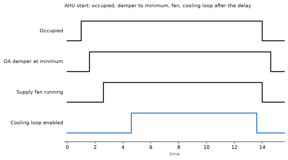
The delay in step 5 is the cheapest fix in the whole sequence. Without it the temperature loop sees a large error the moment the fan starts, winds the valve to 100 percent, and overshoots the setpoint by several degrees before it settles.
Put the loops in a periodic task and slow them down
| Loop | Period | Starting gains | Note |
|---|---|---|---|
| Duct static pressure | 500 ms | Moderate gain, integral around 30 s | Fastest loop on the unit |
| Discharge air temperature | 1 s task, loop tuned slow | Low gain, integral 300 to 600 s | Coil and duct have real dead time |
| Space temperature reset | 10 s | Proportional only is often enough | Resets the discharge setpoint, does not control the valve |
All three belong in periodic tasks, never in the continuous task. A temperature loop with a drifting period is the classic source of the slow hunt that nobody can explain. The setup and the bump test to get the numbers are in PID control in PLC systems, and the older worked example is in PLC PID control automation.
The cooling loop drives the chilled water valve. The economizer takes the same loop output and splits it across the damper range, which is where the sequence needs a decision.
Economizer logic that does not fight the valve
(* 1 second periodic task, CompactLogix 5069-L306ER        *)
(* Changeover: use outside air when it is cooler than the  *)
(* return air by 2 K and below a fixed high limit.         *)

Econ_Available := (OA_Temp_C < RA_Temp_C - 2.0)
                  AND (OA_Temp_C < 18.0)
                  AND NOT OA_Sensor_Fault;

IF Fan_Proven AND Cool_Loop_Enable THEN
    IF Econ_Available THEN
        (* First 50 percent of loop output opens the dampers *)
        OA_Damper_Pct := Min_OA_Pct
                       + (Cool_CV * 2.0) * (100.0 - Min_OA_Pct) / 100.0;
        IF OA_Damper_Pct > 100.0 THEN
            OA_Damper_Pct := 100.0;
        END_IF;
        (* Valve only opens once dampers are wide open *)
        IF Cool_CV > 50.0 THEN
            CHW_Valve_Pct := (Cool_CV - 50.0) * 2.0;
        ELSE
            CHW_Valve_Pct := 0.0;
        END_IF;
    ELSE
        OA_Damper_Pct := Min_OA_Pct;
        CHW_Valve_Pct := Cool_CV;
    END_IF;
ELSE
    OA_Damper_Pct := 0.0;
    CHW_Valve_Pct := 0.0;
END_IF;
The high limit on outside air temperature matters in a humid climate. Dry bulb changeover is simple and it is wrong on a muggy 17 degree day, when the outside air carries more heat in its moisture than the return air does. If the site has that climate, use an enthalpy or dew point sensor and change the first condition.
Stage the compressors with real timers
DX stages need three timers each and they are not optional. Minimum off time protects the compressor from restarting against head pressure. Minimum on time stops the unit hunting. The interstage delay keeps stage two from following stage one by two seconds.
Rung 10: stage 1 call
  ---] [--------] [---------]/[------------( )---
   Cool_Enable  Stage1_Req  Stg1_MinOff.TT   Stage1_Out

Rung 11: stage 2 call, 5 minute interstage delay
  ---] [--------] [--------] [-------]/[-----( )---
   Stage1_Out  Interstage.DN  Stage2_Req  Stg2_MinOff.TT  Stage2_Out
Typical numbers on a packaged rooftop unit are five minutes minimum off, three minutes minimum on, and five minutes between stages. Check the unit documentation, because a scroll compressor and a semi hermetic have different limits, and the warranty follows those numbers.
Stage on a deadband, not on the raw PID output. A one degree deadband around the setpoint stops the stages toggling every time somebody opens a door.
Talk to the building system
| BACnet/IP | Modbus TCP | |
|---|---|---|
| Data model | Objects with names, units, priority arrays, change of value | Raw registers, you supply the meaning |
| Who asks for it | Building management contractors, almost always | Chillers, meters, older equipment |
| Effort on the PLC side | Gateway or a BACnet stack, more configuration | Simple, map and go |
| Commissioning | The BMS integrator can browse your points | Someone maintains a register list in a spreadsheet |
A Logix controller does not speak BACnet on its own. A ProSoft QuickServer style gateway sits between EtherNet/IP and BACnet/IP and exposes your tags as analog and binary objects. Plan the point list early and name the objects the way the BMS integrator expects, because renaming them after the graphics are built is a week of somebody’s life. The naming scheme, the object map and the override rules that go around it are set out in HVAC point names, BACnet objects and overrides that expire. The wider protocol comparison is in communication protocols for PLC and SCADA systems.
One warning on the priority array. A BACnet write from the building system at priority 8 will sit on your command point until it is released at the same priority. Operators who do not know that end up with a damper stuck at the value somebody typed in six months ago.
Field notes
The discharge sensor that read four degrees low. A single point sensor was mounted 300 mm downstream of the chilled water coil, in the cold stripe coming off the bottom third of the coil face. The loop chased a temperature the building never saw. An averaging element strung across the duct moved the reading up by 4 K and the hunting stopped. Sensor placement is control, not instrumentation.
Integral windup every Monday. The building came back from a weekend at 28 degrees inside. The temperature loop ran with the valve at 100 percent for forty minutes, banking integral the whole time, then held the valve wide open for another twenty minutes past setpoint. Two changes fixed it: hold the integral while the output is saturated, and use a lower gain during morning warm up.
Freeze stat wired only to a PLC input. A coil froze and split over a holiday weekend because the freeze stat went to an input card and the logic that stopped the fan was in a program that had been put in test mode. The freeze stat and the smoke detector belong in the fan starter control circuit, in hard wire, and the PLC input is only for the alarm message.
Damper actuator on the wrong signal range. A 2-10V actuator on a 0-10V output. At zero percent command the actuator sat at its stop, and at 20 percent it was still closed, so the minimum outside air position was wrong all winter. Match the range or scale the output, and check the actuator with a meter and a hand crank before you believe the graphic.
Frequently asked questions
Can a PLC replace a DDC controller in a plant room?
For an air handler or a chiller plant, yes, and you get better logic tools. What you give up is the library of prebuilt HVAC objects and a BMS front end that facilities staff already know.
How fast should the static pressure loop run?
Around 500 ms is fine. Anything faster follows duct turbulence rather than the actual pressure, and the fan speed jitters.
Why does the supply fan hunt at low load?
Usually the static setpoint is too high for the number of boxes open, or the pressure sensor tap sits too close to a bend. Try a setpoint reset based on the most open terminal box before you touch the gains.
Do I need a separate sensor for the economizer changeover?
You need outside air temperature, which you probably already have. Dew point or enthalpy needs a combined sensor and is worth it in humid climates.
How do I alarm on a sensor failure?
Trap the raw signal outside its expected range and hold the loop. An open 4-20 mA loop reads as a very low temperature, which makes a cooling loop close the valve on a hot day. The instruction to raise it is covered in PLC analog alarm ALMA.
Next step
Tune the temperature loop with a proper bump test rather than by feel, using the method in PID control in PLC systems. Then set up a trend on discharge temperature, valve position and fan speed on the same chart, as described in PLC trend chart settings and monitoring. Most HVAC arguments end the moment somebody produces that trend.