The robot reads its fieldbus inputs on its own interpolation cycle, roughly every 8 ms, while your cell task sets Start_Cycle for one 20 ms scan and drops it again. That works until a safety scanner goes on the same switch and jitter goes up, and then the cell sits with the arm at home and the PLC convinced it sent a start. Good PLC robot integration comes down to three decisions: who owns the cycle, which signals are levels instead of pulses, and what happens when one side stops in the middle of a move. This walkthrough builds a pick and place cell on a CompactLogix with a FANUC R-30iB Plus over EtherNet/IP, with the notes you need for ABB and KUKA on the same pattern.
The cell here takes parts off an indexing conveyor and loads them into a fixture.
The cell
| Item | This example |
|---|---|
| Controller | 5069-L330ERM CompactLogix 5380, Studio 5000 v33 |
| Robot | FANUC R-30iB Plus, EtherNet/IP adapter, rack 89 slot 1, 32 bytes each way |
| Safety | Compact GuardLogix 5069-L306ERMS2, fence interlock and a light curtain on the load side |
| Network | Managed switch, robot on its own VLAN with the cell devices |
| Cell task | Periodic CellTask, 20 ms, priority 8 |
| Robot connection | RPI 24 ms, connection timeout at the default multiplier |
Twenty bytes would be enough for this cell. Take 32 anyway. Adding a byte later means an offline edit on both sides and a robot restart, and you will want spare bits within a month.
Step 1: Decide who owns the cycle, then write it down
One rule saves weeks of argument: the PLC owns the sequence, the robot owns the motion. The PLC decides when a part may be picked, which program runs and when the fixture clamps. The robot decides how the arm gets there. As soon as the robot program starts making cell decisions, for example waiting on its own timer for the conveyor, you have two masters and the failure modes multiply.
That means the robot program is short. Wait for a start bit, move, set a done bit, go home, loop. Everything else lives in ladder or Structured Text where the maintenance electrician can see it at 3am without a teach pendant.
Step 2: Map the robot signals into a UDT
On FANUC, two groups matter. The UOP signals are the controller’s own interface and the user I/O is your application data. Assign the UOP to the EtherNet/IP rack, put the robot in Remote mode, and check $RMT_MASTER is set for remote control before you wonder why nothing starts.
| Direction | Signal | Use |
|---|---|---|
| PLC to robot | UI[1] IMSTP, UI[2] Hold, UI[3] *SFSPD | Normally closed. The PLC must hold these ON or the robot will not move. |
| PLC to robot | UI[5] Fault Reset, UI[6] Start, UI[8] Enable | Reset from the HMI, start after a hold, general enable |
| PLC to robot | UI[9] to UI[16] PNS1 to PNS8, UI[17] PNSTROBE, UI[18] PROD_START | Program number select |
| Robot to PLC | UO[1] CMDENBL, UO[2] SYSRDY, UO[3] PROGRUN, UO[6] FAULT, UO[7] ATPERCH | Ready, running, faulted, at perch |
| Both | User DI/DO | Start_Cycle, Cycle_Done, Gripper_Closed, Part_Taken, Zone_Request |
Build two UDTs, Robot_Cmd and Robot_Sts, and COP them onto the connection tags in one place. Nothing else in the project should touch Robot:I.Data[3].5 directly. When the robot integrator moves a bit in month six you change one copy instruction instead of hunting through forty rungs. The UDT mechanics are in user defined datatype UDT usage examples.
ABB and KUKA use different names for the same idea. On an IRC5 you configure system inputs for Motors On, Start at Main and Program Reset, and system outputs for Motors On State and Execution Error. On a KRC4 with Automatic External you drive $MOVE_ENABLE, $DRIVES_ON, $EXT_START and $CONF_MESS, and read $PERI_RDY, $PRO_ACT and $ALARM_STOP. The signal names change, the handshake does not.
Step 3: Select the program by number, not by a bit per program
Give every part a program number and send it as a binary value. On FANUC that is PNS: put the number on PNS1 to PNS8, pulse PNSTROBE, wait for the robot to acknowledge with SNACK, then pulse PROD_START. The robot runs PNS0007 for program 7, so the program names on the pendant have to match the numbers in your recipe table exactly.
One bit per program looks simpler and falls apart at eleven part types. A number also gives you something to log, compare against the order from MES and show on the HMI when the operator asks why the robot picked the wrong nest.
Step 4: Make the handshake out of levels and acknowledgements
This is where cells actually fail. The robot reads its fieldbus inputs on its own interpolation cycle, roughly every 8 ms on an R-30iB, and your ladder might set a bit for a single 20 ms scan. That usually works. The morning it does not, the cell sits there with the robot at home and the PLC convinced it sent a start.
So never use a one-shot for a cell signal. The PLC holds Start_Cycle true until it sees Robot_Busy come back, then drops it. The robot holds Cycle_Done until it sees Start_Cycle drop. Each side clears its own signal only after seeing the other side react.
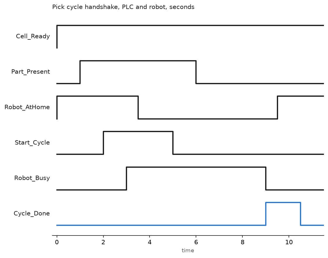
(* CellTask, 20 ms periodic, routine RobotHandshake, Structured Text *)
CASE Cell_Step OF

  0:  (* wait for the robot to be ready and parked *)
      IF Rbt.Sts.SysReady AND Rbt.Sts.AtPerch AND NOT Rbt.Sts.Fault THEN
          Cell_Step := 10;
      END_IF;

 10:  (* part in the pick position and fixture empty *)
      IF Part_Present AND Fixture_Empty AND Guard_Closed THEN
          Rbt.Cmd.PrgNo := Recipe[Current_Part].RobotPrg;
          Rbt.Cmd.Strobe := 1;
          Cell_Step := 20;
      END_IF;

 20:  IF Rbt.Sts.StrobeAck THEN
          Rbt.Cmd.Strobe := 0;
          Rbt.Cmd.StartCycle := 1;      (* level, not a pulse *)
          Cycle_Tmr.PRE := 12000;       (* watchdog, 1.5 times worst cycle *)
          Cycle_Tmr.TimerEnable := 1;
          Cell_Step := 30;
      END_IF;

 30:  IF Rbt.Sts.Busy THEN
          Rbt.Cmd.StartCycle := 0;      (* robot has it, release the request *)
          Cell_Step := 40;
      END_IF;

 40:  IF Rbt.Sts.CycleDone AND Rbt.Sts.AtPerch THEN
          Part_Count := Part_Count + 1;
          Cycle_Tmr.TimerEnable := 0;
          Cycle_Tmr.ACC := 0;
          Cell_Step := 0;
      END_IF;

END_CASE;

TONR(Cycle_Tmr);
IF Cycle_Tmr.DN THEN
    Robot_Timeout := 1;                 (* alarm, hold the robot, do not retry *)
    Rbt.Cmd.StartCycle := 0;
END_IF;
The watchdog is not optional. Without it a lost handshake looks exactly like a slow cycle, and the operator will stand and watch for four minutes before calling anyone.
Step 5: Keep the safety circuit out of the handshake
The bits above are standard I/O and they prove nothing about safety. Fence interlocks, the light curtain and the robot’s own safe stop belong in safety-rated logic with dual channel devices, a safety task and a safe output to the robot’s safety inputs. Modern controllers also carry internal safe zones, DCS on FANUC and SafeMove on ABB, which limit the arm to a volume regardless of what the program does. Use them where an operator loads a nest inside the cell envelope.
Two practical points. A muted light curtain needs the mute sensors sequenced and timed out, or someone will learn to walk through it behind a pallet. And the robot’s decel stop through *Hold is a process stop, not a safety stop; treat it as a convenience and never as protection. The wiring and logic side of that split is covered in implementing PLC safety interlock systems.
Step 6: Set the RPI and the task rate so the cycle time is real
Put the robot connection at an RPI near your cell task rate. 24 ms against a 20 ms task is fine. Setting the RPI to 2 ms because the dropdown allows it just multiplies packets per second on the switch and gains nothing, since the robot only looks at its inputs every 8 ms anyway.
Check three numbers after commissioning: cell task scan time, the robot connection’s actual packet interval, and the measured handshake latency from Start_Cycle to Robot_Busy. If the last one is drifting upwards, something on that switch is growing, usually a vision camera streaming images. PLC scan time and cycle time has the method for the first one.
Field notes
The one-shot that worked for eight months. A cell started with an OSR driving the robot start bit. It ran through summer. In September a new safety scanner went on the same switch, jitter went up, and the cell stalled roughly twice a shift with no fault on either side. The fix was ten minutes of logic: hold the level, wait for busy, drop it.
Normally closed inputs treated as commands. A colleague wired UI[1] IMSTP and UI[2] Hold as though a 1 meant stop. The robot sat with CMDENBL off and no obvious fault. Those three UOP inputs are normally closed. The PLC has to hold them on for the robot to accept a start, which is exactly backwards from every other bit in the interface.
At home that was not at home. The robot set an AtHome
Program numbers out of step with the pendant. A part was added as recipe 12, but the pendant program was named PNS012, three digits. The robot never acknowledged the strobe and the PLC waited forever. Name the programs from the recipe table and check them on the pendant before handover.
Frequently asked questions
Should the gripper be controlled by the PLC or the robot?
By the robot, in almost every case. The valve sits on the arm and the timing belongs with the motion. The PLC should see the confirmation sensors so it can interlock on a dropped part.
EtherNet/IP or PROFINET?
Follow the controller family. Logix with FANUC or ABB on EtherNet/IP, S7-1500 with KUKA or ABB on PROFINET. Mixing them means a gateway, and a gateway adds latency plus another device that can fail at 2am. Background on the first is in EtherNet/IP PLC communication.
How do I recover after an E-stop without a full reset?
Reset the safety circuit, then fault reset with UI[5], then the robot needs an enable and a start to continue from where it stopped. Whether it can continue depends on whether the program pointer survived. Test this on the real cell before handover, because operators will hit E-stop mid-move in week one.
Can the PLC read the robot position?
Yes, over the same connection if the integrator maps position registers into the I/O area, or through the robot’s own protocol. Useful for monitoring and for zone requests between two robots sharing space, but do not use it to interlock motion in real time.
What causes a cell to lose 2 seconds of cycle time nobody can explain?
Usually a wait in the robot program for a signal that the PLC sets late, or a conveyor index that is not overlapped with the robot’s return move. Log timestamps for start, busy, done and at perch, and the gap shows itself in one shift.
Next step
Once the handshake is solid, the next gains come from overlapping motion with the rest of the cell, which needs real coordinated moves rather than discrete I/O. Start at PLC motion control. If the cell has to report parts and faults upward, integrating PLC with MES covers the data side.