A 1756-IF8 analog input in integer mode lands on roughly -20,030 counts at 4 mA and 30,920 at 20 mA, which are not numbers anybody memorises. If the value in front of you is 3277, the card in the rack is a 1769-IF4 or 1769-IF8 running the Scaled-for-PID data format, and none of the 1756 scaling advice you have been reading applies to it.
Both of those deserve unpacking, because the gap between them is where an afternoon goes.
The short version for the 1756-IF8: there is no 4-20 mA range on the module, only 0…20 mA; the loop needs a jumper on the RTB before any current flows through the module’s own sense resistor; and in floating point mode you tell the module 4 mA and 20 mA yourself and it hands back engineering units, so the counts never appear at all.
Everything below is the 1756-IF8 on 1756-UM009G, March 2025, in a 1756 chassis with Studio 5000 v33.
The range you want is not on the list
Open the module properties and the Input Range dropdown for a 1756-IF8 offers four choices: -10 to +10V, 0 to 5V, 0 to 10V, and 0…20 mA.
No 4…20 mA.
That is not an oversight and it is not the module being basic. The 1756-IF8 measures the whole 0…20 mA span in hardware, all the time, at the same resolution, and the 4 mA at the bottom of your transmitter’s range is just a point inside it. Where the range gets turned into something meaningful is the scaling, and what you do there depends entirely on which of the two data formats the module is in — a choice that also decides whether you ever see a count at all. Note the contrast with the smaller family while you are here, because it is the root of the confusion this article started with: a 1769-IF4 does have separate 4 mA to 20 mA and 0 mA to 20 mA input ranges in its own manual, listed as two different rows of the same table, and a 1769-IF4 will happily let you pick the wrong one. Two Rockwell analogue input cards, two different answers to the same question, and nothing on either dialog to warn you that the other card behaves differently.
The jumper, and the 249 Ω behind it
This is the wiring detail that stops more 1756-IF8 channels from working than anything else, and it takes one wire.
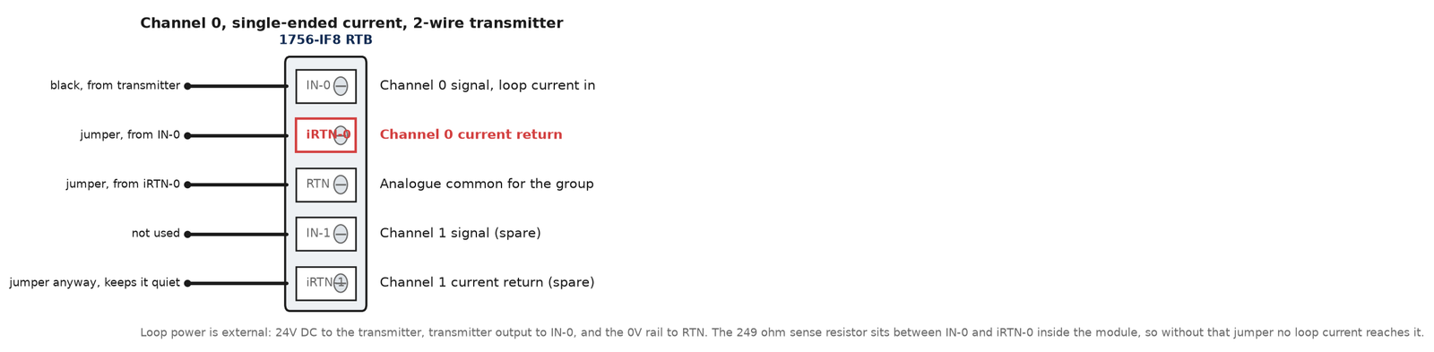
Inside the module, between the IN-x and iRTN-x terminals of every channel, sits a 249 Ω current loop resistor — 1756-UM009 prints that note under every current wiring diagram in the chapter. That resistor is the thing your loop current develops a voltage across, and the module measures that voltage. It is not in circuit until you put it there. On the RTB you fit a jumper from IN-x to iRTN-x, and the loop current then runs in on IN-x, through the 249 Ω, and out at iRTN-x. Leave the jumper off and the current has nowhere to go through the module at all. There is a second half of it for single-ended wiring that catches people separately, and the manual states it as a rule rather than a suggestion: for current applications, all terminals marked iRTN must be wired to terminals marked RTN. So a single-ended current channel wants two wires added to the RTB before you land the field cable — IN-0 to iRTN-0, and iRTN-0 across to RTN.
Loop power is yours to supply. The module does not source it.
Every current wiring diagram in the manual shows either user-provided loop power for a 2-wire transmitter or a separate device supply for a 4-wire one, and the module sits in the loop as a passive burden and nothing else. A 2-wire transmitter takes 24V out of the panel, the loop returns through the module and back to the 0V rail. A 4-wire transmitter is powered from the panel independently and its current output pair is what lands on IN-0 and iRTN-0. Both work; they wire differently; and a 4-wire device wired as if it were 2-wire is the second most common way to get a dead channel.
One more decision goes with the wiring, and it costs you channels. Single-ended gives you all 8 channels on a 1756-IF8. Differential gives you 4. High-speed differential gives you channels 0 and 2 only, and the manual says so in as many words — when operating in two-channel, high-speed mode, only use channels 0 and 2. Pick the mode before the panel is built, because it changes how many transmitters fit on the card.
What the 1756-IF8 analog input returns in integer mode
Pick integer mode and the scaling dialog goes away. The manual is direct about it: scaling isn’t available in integer mode, the low signal of your application range equals -32,768 counts and the high signal equals 32,767 counts.
Here is the part that trips everyone.
For a 1756-IF8 on the 0…20 mA range, those two endpoints are not 0 mA and 20 mA. They are 0 mA at -32,768 counts and 20.58 mA at 32,767 counts. The extra 0.58 mA is headroom above the range so the module can still report an overrange rather than saturate at exactly 20.00 mA.
Which makes the counts at the numbers you care about awkward, so here they are, worked from those two published endpoints:
| Loop current | Integer counts (1756-IF8, 0…20 mA) |
|---|---|
| 0 mA | -32,768 |
| 3.2 mA | -22,578 |
| 4 mA | -20,030 |
| 8 mA | -7,293 |
| 12 mA | 5,445 |
| 16 mA | 18,182 |
| 20 mA | 30,920 |
Those are arithmetic, not a table Rockwell prints. The manual gives you the two ends and the linearity; the middle is division. Copy them onto the drawing anyway, because the first time a 4-20 mA transmitter reads -20,030 and somebody decides the channel is broken, that number is the proof it is not.
And if you are doing the scaling in ladder, the span is 50,950 counts across 4 to 20 mA rather than a round number. Which is exactly why floating point mode exists.
Floating point mode, and what the four boxes mean
Set the data format to floating point and the module hands the controller a REAL instead, scaled per channel by four values you supply: Low Signal, High Signal, Low Engineering and High Engineering.
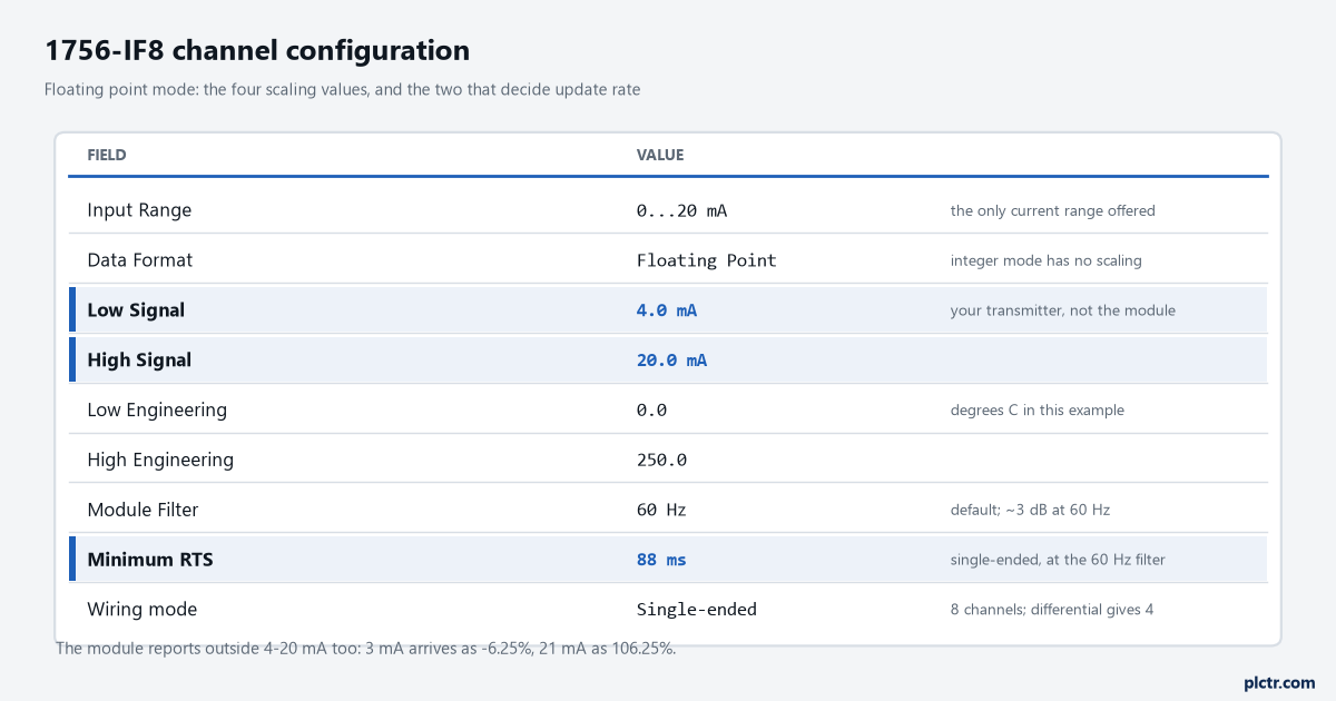
Low Signal 4 mA, High Signal 20 mA, Low Engineering 0, High Engineering 250 for a 0-250 °C transmitter, and the tag reads degrees. That is the whole job, and it is why most 1756-IF8 channels never need a line of scaling code anywhere in the project.
Two things about it are worth knowing before you trust it.
The module does not clamp at your endpoints. Rockwell’s own worked example scales 4 mA to 0% and 20 mA to 100%, and then shows 3 mA arriving as -6.25% and 21 mA as 106.25%. The module keeps reporting outside the window you defined, which is a feature — it is how you see a transmitter drifting low rather than having the reading pinned at zero — but it means anything downstream has to expect negatives. A negative pressure handed to a PID loop drives the output hard against a limit, so clamp it deliberately in logic or let an analogue alarm instruction do the work before it reaches the loop.
And scaling buys you nothing in precision. The manual is explicit: module resolution is fixed, and it does not change regardless of what data format you choose or how you scale your module in floating point mode. Scaling changes the units on the number, not how many distinguishable steps are in it.
So where does 3277 come from
The Compact I/O family, on a data format the 1756 modules do not have.
1769-UM002 describes four input data formats for the 1769-IF4 and 1769-IF8: Raw/Proportional, Engineering Units, Scaled-for-PID and Percent Range. The third is the one that produces the number. Rockwell’s description of it: the value presented to the controller is a signed integer with zero representing the lower user range and 16383 representing the upper user range, and Allen-Bradley controllers such as the MicroLogix 1500 use this range in their PID equations. Full scale, including the over and under range headroom, runs -410 to 16793. Now do the arithmetic that everyone arrives at without knowing they have. A channel on the 0 mA to 20 mA input range, in Scaled-for-PID, maps 0 mA to 0 and 20 mA to 16383. Feed it a 4-20 mA transmitter at its bottom end and 4 mA is a fifth of the span: 0.2 × 16383 = 3276.6, which the module hands over as 3277. Not a fault, not a wiring error, not a dead transmitter — a fifth of full scale, reported accurately, by a card that was told the signal starts at zero.
So 3277 is a correct reading of a healthy transmitter on a card configured for the wrong range.
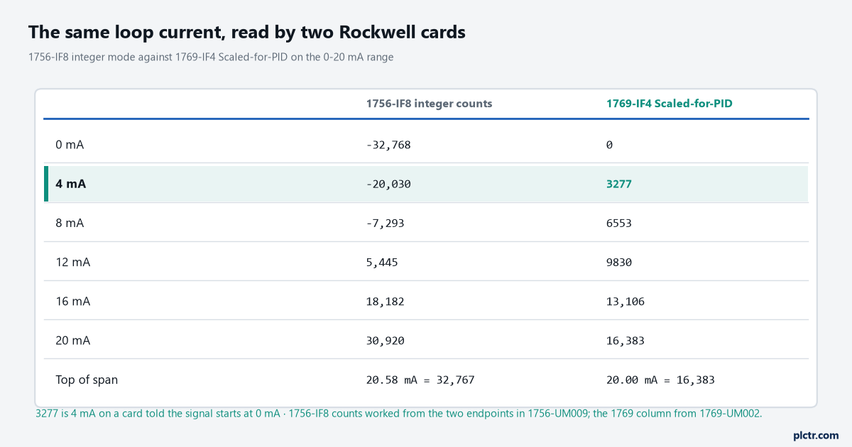
The fix on that card is one dropdown, because 1769-UM002 lists 4 mA to 20 mA as its own input range, and on that range the same manual’s table puts 4.0 mA at 0 and 20.0 mA at 16383. Change the range, download, and the same loop reads 0 at the bottom instead of 3277. Nobody needs to touch the scaling maths, which is what most people try first — and the reason that dead end is so convincing is that a scaling correction of exactly the right size does make the displayed value right, at the cost of 20% of your resolution and a channel that will read wrong again the day somebody replaces the module.
If you are landing the same signal on a Siemens card instead, the equivalent decisions are covered in scaling an analogue input in FBD.
Why the number moves slower than your RPI
Set the RPI to 5 ms on a 1756-IF8 and the value in the tag will still change every 88 ms, and there is nothing wrong with either.
RPI decides how often the module multicasts.
RTS — real-time sampling — decides how often it actually scans its channels before multicasting, and the module filter sets a floor under the RTS you are allowed to ask for. The default module filter is 60 Hz, which the manual says provides approximately 3 dB of filtering of a 60 Hz input, and that setting carries a minimum RTS of 88 ms in single-ended wiring, 44 ms differential, 22 ms high-speed differential. Choose the 10 Hz filter for better mains rejection — the manual recommends it for optimal 50…60 Hz noise rejection, better than 80 dB — and the single-ended minimum RTS goes to 488 ms. Go the other way to 1000 Hz and single-ended drops to 18 ms, but effective resolution falls from 16 bits to 12. There is a footnote worth reading twice as well: worst case settling time to 100% of a step change is double the RTS sample times.
That is the trade laid out in one table. Noise rejection, update rate, resolution — pick two.
For a tank level on a 500 ms PID, leave the filter alone. For a pressure signal feeding a fast interlock, work out what the 12-bit resolution at 1000 Hz actually costs you in engineering units before you go there.
When the wire comes off
The 1756-IF8 has no open-wire bit. What it has is wire-off detection, and it reports through the range bits you already have.
In current applications, the manual gives two causes: the RTB has been disconnected from the module, or the signal wire and/or the jumper wire have been disconnected.
The channel then drives to its underrange or overrange value and sets ChxUnderrange or ChxOverrange. That is the whole mechanism — there is no separate diagnostic to read, and the tag names are the ones already sitting in the module-defined structure alongside ChxFault, ChxCalFault, ChxRateAlarm and the four alarm bits.
Which is another argument for 4-20 mA over 0-20 mA in the field, and it has nothing to do with data formats. A broken wire on a 4-20 mA loop reads 0 mA, and 0 mA is below the bottom of a live signal, so it is distinguishable from a real reading. On a 0-20 mA loop a broken wire reads exactly the same as a legitimate zero.
Alarm on the underrange bit, not on the value.
What to check next
Put the channel’s raw tag on a watch window and a meter in series with the loop at the same time, and compare. If the meter says 4.0 mA and the tag says -20,030 in integer mode, the wiring and the range are right and your scaling is the problem. If the meter says 4.0 mA and the tag is pinned at -32,768, the jumper is missing or iRTN never got carried to RTN, and no amount of configuration will fix it — that one is a screwdriver.
If the meter reads nothing at all, the loop supply and the transmitter come first, then the module fault bits, then the card. And if the module was added to the tree by somebody else, open its properties and confirm the wiring mode matches the panel before you trust a single channel above 3 — the New Module dialog does not know how the RTB was landed, and the difference between single-ended and differential is four channels that look present and read nonsense.