PNP sensor wiring is decided on the input card’s spec sheet, and almost nobody reads that row. Under Voltage category, a 1756-IB16 says 12/24V DC sink and a 1756-IV16 says 12/24V DC source — same form factor, same 16 points, same 5V off-state threshold, and only one of them will ever see a PNP sensor turn a point on.
A PNP sensor sources current out of its signal wire, so the card has to sink it.
That is the whole rule, and the reason it gets reversed so often is that the word describes opposite jobs depending on which end of the wire you are holding. Sensor sources, card sinks. Say it once in that order and it stops flipping.
The rest of this is how to tell which card you have, what the failure actually looks like, and the leakage current that turns a correct pairing into an input you cannot switch off.
The word means two different things
Sinking and sourcing describe where the current comes from, not what the device is.
A PNP sensor connects its signal wire to the positive rail when it detects something. Current flows out of the sensor, through the field wire, into the input, and back to 0V through the card. The sensor is the source. The card is the sink. On a card like the 1756-IB16 that means the group common goes to DC COM — the negative rail — and every point on that group expects to be fed 24V from somewhere outside the module. An NPN sensor does the opposite. It connects its signal wire to 0V, so the current has to come from the card, out through the field wire, and down into the sensor. Now the card is the source and the sensor is the sink, and the card’s common goes to +24V instead. Nothing about either arrangement is more correct than the other; the machine builder picked one years ago and every sensor on the machine has been that type ever since, which is exactly why the one odd sensor somebody ordered as a replacement is the one that will not work.
Both descriptions are correct. They are just descriptions of different objects, and the moment somebody writes “sinking sensor” on a drawing without saying which end they mean, the next person has a coin flip.
The PNP sensor wiring diagram that settles it
Rockwell draws both cases on one page and labels them, which is worth more than any amount of explaining.
The wiring diagram for the 1756-LSC8XIB8I in 1756-TD002 shows an Allen-Bradley Bulletin 872 3-wire DC proximity sensor twice. The Normally Open PNP version goes to the terminal group labelled Module Sink Input Wiring. The Normally Open NPN version goes to the group labelled Module Source Input Wiring. Same module, same page, two sensors, two labels.
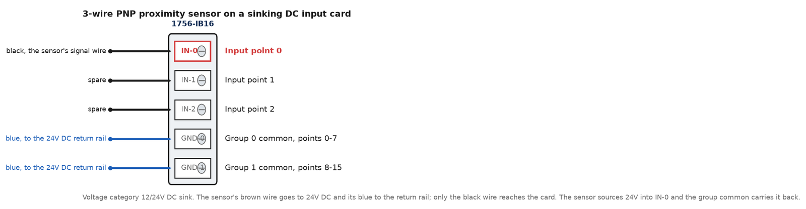
That same figure also settles the colour code, which people usually take on trust from a forum post. Brown goes to 12…24V DC. Blue goes to 12…24V DC Return. Black is the signal, and it is the one that lands on the input terminal. Three wires, and only the black one ever moves when you change your mind about the card.
What it looks like when it is wrong
Nothing dramatic. That is the problem.
Land a PNP sensor on a sourcing card and the point never turns on.
The sensor is fine, its LED lights when the target is in front of it, and a meter from the signal wire to 0V reads 24V exactly as the datasheet says it should. What is missing is a return path: the card wants to push current out of that terminal and the sensor is pushing back, so the two of them sit there both trying to source and nothing flows. On a standard 1756 DC input the specification lists reverse polarity protection, so this is not usually a way to damage anything — but that is an inference from the spec line rather than a sentence any vendor prints, so treat “no harm done” as likely rather than guaranteed and pull the wire before you go looking for something else.
The first conclusion everybody reaches is that the card is faulty.
It is a reasonable conclusion. The input LED is dark, the meter reads 24V at the terminal, and the obvious explanation is a dead point. So the card gets swapped, the new card behaves identically, and only then does somebody go and read the catalogue number on the side of it. An hour, a spare module out of the cabinet, and a fault that was never in the rack. If you have got as far as swapping a card, work the rung back to the terminal instead and check what the common of that group is tied to. DC COM means sinking. +24V means sourcing. It takes ten seconds with a meter and it is the only test that actually answers the question.

The leakage number, and the card that wants more of it
Here is the failure that is harder than the wiring one, because everything is correct and the input still will not switch off.
Every DC input carries an off-state specification, and on a 1756-IB16 it is two numbers.
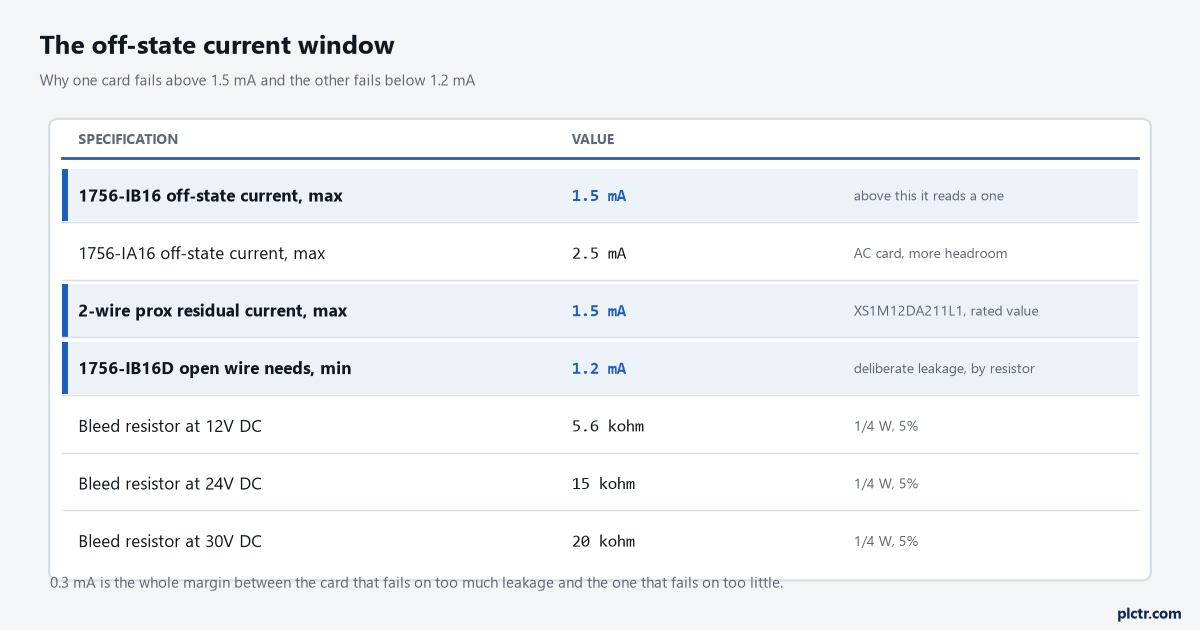
Off-state voltage max 5V, off-state current max 1.5 mA. Below 5V and below 1.5 mA, the card reads a zero. Above them, it starts reading a one. The on-state minimum is 2 mA at 10V DC, so the genuinely undefined band is narrow — and a device that leaks 1.6 mA when it is supposed to be off sits in it permanently. Now look at what a real sensor leaks. A Telemecanique XS1M12DA211L1, a 2-wire proximity sensor, publishes a maximum residual current of 1.5 mA in the open state, because a 2-wire device has to keep drawing enough current through the load to power its own electronics even when it is telling you nothing is there. That figure is not a defect. It is the rated, in-specification, working behaviour of the part, and it lands exactly on the 1756-IB16’s off-state maximum with nothing to spare. Two of those on one point, or one of them plus a bit of cable capacitance on a long run, and the input is on all day. The same arithmetic applies to a solid-state output driving a PLC input, and to a triac output on an AC card, which is why 1756-IA16 gets a more forgiving 2.5 mA off-state maximum — more headroom, same trap.
The fix is a bleed resistor across the input, sized so the leakage current mostly goes through it instead of the input.
And now the part that makes the whole thing make sense. Rockwell publishes exactly that resistor table — but for the opposite reason.
A 1756-IB16D is the diagnostic version of the same card, and it detects an open field wire. To do that it has to see some current flowing while the input is off, because a broken wire and a genuinely open contact look identical otherwise. So the diagnostic specification reads: open wire, off-state leakage current 1.2 mA min. The card requires at least 1.2 mA of leakage before open-wire detection works at all, and 1756-TD002 gives you the resistor to create it deliberately:
| Supply voltage | Recommended leakage resistor, 1/4 W, 5% |
|---|---|
| 10V DC | 3.9 kΩ |
| 12V DC | 5.6 kΩ |
| 24V DC | 15 kΩ |
| 30V DC | 20 kΩ |
Read those two specifications together and the window is obvious. The standard card fails above 1.5 mA. The diagnostic card fails below 1.2 mA. Three hundred microamps is the entire design margin, and it is why a resistor fitted for one card is a fault on the other, and why an installation that worked for years starts glitching after somebody standardised the spares.
Siemens says it in its own words
The SIMATIC spec tables carry a row called Sinking/sourcing input, and they fill it in plainly.
A DI 32x24VDC BA, catalogue 6ES7521-1BL10-0AA0, reads Sinking input in that row. Its thresholds go with it: signal “0” from -30 to +5 V, signal “1” from 11 to 30 V, input characteristic curve according to IEC 61131 type 3. So the Siemens sinking input and the Rockwell sinking input want the same thing — a device that sources 24V into the point — and the vocabulary lines up even when nothing else about the two systems does.
You will also meet the older German phrasing in Siemens documents and in translations of them. P-reading and M-reading, from Plus and Minus: a P-reading input is looking for the positive rail to appear at its terminal, which is the sinking input that pairs with your PNP sensor. M-reading is the other one. When a datasheet gives you P and M rather than sink and source, that is what it is saying.
The cards that take either
Some modules do not force the choice, and it is worth knowing which before you order.
On the Rockwell side the individually isolated inputs are the ones.
A 1756-IB16I or 1756-IB16IF lists its voltage category as 12/24V DC sink/source, and the wiring chapter shows Module Source Input Wiring and Module Sink Input Wiring as two options for the same module. CompactLogix does it at the group level: a 1769-IQ16 is a 24V DC sink/source input module and its wiring diagram labels adjacent terminals +DC (sinking) and −DC (sourcing), so you pick per group as you land the wires. The specialty 1756-LSC8XIB8I counter card in the diagram above is sink/source for the same reason.
Siemens does it at the CPU. The onboard digital inputs on an S7-1200 are listed as sink/source, and the wiring tables repeat the instruction on every CPU variant: connect the negative to M for sinking inputs, or the positive to M for sourcing inputs. One terminal, two meanings, decided by what you land on the common.
Isolation is what you are paying for in every one of those cases. A card that can do either has to keep each point or each group independent, which costs money and points per card, and that is the honest reason the plain 1756-IB16 exists at all.
When the wrong card is already in the rack
Three ways out, and the order matters.
Change the sensor first if you can. A 3-wire prox in NPN instead of PNP is usually the same body, the same price and a different part number, and if the machine is not built yet this costs nothing at all. Interposing relays are the next one — one relay per point, the sensor drives the coil, the contact feeds the input from whichever rail the card wants — and it works perfectly, costs a relay and a base per point, and adds a moving component that eventually sticks. Doing that for two points is sensible engineering. Doing it for sixteen means you bought the wrong card and are now paying for it a second time, in panel space, in wiring hours and in a row of relays that somebody will be replacing one at a time for the next decade.
Or change the card, which is the right answer for sixteen points and needs one thing checking first: the module type in the I/O tree has to change too, not just the metal. Swapping a 1756-IB16 for a 1756-IV16 without updating the configuration gets you a keying mismatch and a module that will not connect, which is a different fault report entirely and is covered with the rest of the I/O fault causes.
What does not work is wiring the sensor’s blue wire to the input and calling it a common. People try it. The sensor’s blue is its own supply return, not a switched contact, and using it as one puts the sensor’s supply current through your input.
What to check next
Meter from the group common terminal to 0V on the card that is giving you trouble, before anything else. Near zero means the card sinks and wants PNP. Near 24V means it sources and wants NPN. That single measurement resolves most of what this article covers, and it does not require finding the drawing.
Then, if the point is stuck on rather than stuck off, put a meter in series and read the actual off-state current rather than assuming it. Anything approaching 1.5 mA on a standard DC input is your fault, whatever the sensor’s LED says, and the answer is a bleed resistor rather than a new sensor.
The same choice comes up again on the output side and on analogue, where the equivalent decision is which end supplies the loop power — that one is in reading a 4-20 mA transmitter into a 1756-IF8, and the wider ordering checklist for a rack is in PLC I/O modules: sinking, sourcing, keying, scaling. If the sensor in question is feeding a counter rather than an ordinary point, the wiring rules are the same but the speed limits are not, which is the encoder side of it.