The PIDE gains are not in the units the number next to them suggests. A PIDE in its independent form wants IGain in units of 1/minutes. The classic PID instruction, in what Rockwell also calls its independent form, wants .KI in 1/seconds. Both manuals print those units plainly, in the parameter table, four hundred pages apart, and the number that means a 48 second reset is 1.25 on one block and 0.0208 on the other.
Type one into the other and your integral action is out by a factor of 60. In the fast direction.
That is the trap this article is really about, but it is not the first thing to fix on a new loop. In order: get the scaling right, get the timing mode right, get the control action right, and only then go and bump the thing. Gains entered against wrong spans are just a different set of wrong numbers.
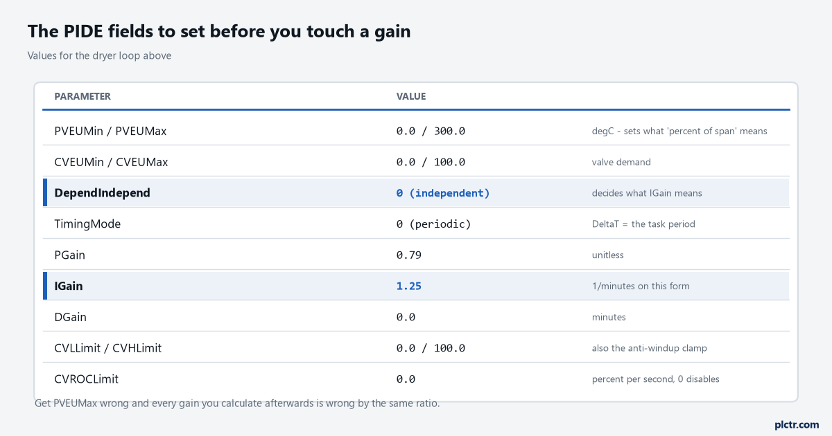
DependIndepend and PVEUMax are highlighted because between them they decide what every gain below them means. Neither is a tuning parameter and both change the tuning.
Span first, because it silently scales every one of the PIDE gains
Everything below this heading is arithmetic, not taste.
PIDE works in percent of span internally. The manual gives the arithmetic in one line each: PVPercent = ((PV - PVEUMin) x 100) / PVSpan, where PVSpan = PVEUMax - PVEUMin, and on the way out CVEU = (CV x CVEUSpan / 100) + CVEUMin.
So PVEUMax is not a display preference. It is a divisor.
Leave PVEUMax at a default of 100 on a transmitter that actually reads 0 to 300 degC and every error the block computes is three times larger than the real one, which makes every gain you calculate afterwards three times too big. The loop will be unstable and the gains will look reasonable, which is the worst combination to walk into. Set PVEUMin and PVEUMax to the transmitter’s real range, set CVEUMin and CVEUMax to the range of whatever the output actually drives, and write both pairs on the loop sheet. If the raw end of that chain is still in doubt, the counts a card really returns are a separate argument and a 4-20 mA transmitter into a 1756-IF8 settles it.
While you are in there, set CVLLimit and CVHLimit too. They are not only alarm points: the manual describes them clamping CV in Auto and Cascade/Ratio, and in Manual when CVManLimiting is true, which makes them the anti-windup limits as well. A PIDE left with those at defaults on a loop that sits against a stop for two hours is a PIDE that will take a long time to come back.
Where the loop gets its clock
TimingMode on a PIDE takes three values, and the default is 0, periodic.
The manual is direct about what that buys you. When the PIDE instruction is used in a periodic task and in periodic timing mode, it automatically uses the periodic task’s update rate as its delta t update time. Put the block in a 500 ms periodic task and DeltaT is 500 ms, with nothing to configure.
Run it in a continuous task and the rule changes. The timing table in the Function Block Attributes chapter says that for an event or continuous task, DeltaT
DeltaT in order for the control algorithm to properly calculate the process output, and if DeltaT varies, a discontinuity occurs in the process output. It goes on to list what causes one, and two of those entries are ordinary programming decisions rather than faults — the instruction not being executed during a scan, and the instruction being executed more than once in a task. A PIDE inside a conditional JSR, or a PIDE called twice because somebody duplicated a rung, is a documented discontinuity rather than a mystery.Put process loops in a periodic task. This is the whole reason function block execution order is worth understanding before you wire one.
There is one more line in that chapter that decides the fourth section of this article, so note it now. The update of the process input needs to be synchronized with the execution of the task, or sampled 5 to 10 times faster than the task executes, in order to minimize the sampling error between the input and the instruction.
Five to ten times faster. A PIDE in a 500 ms task wants its analogue input arriving every 50 to 100 ms.
The bump test, and the three numbers you take off it
Loop in Manual. Process settled.
One step on the output, big enough to see above the noise and small enough that nobody rings you about it.
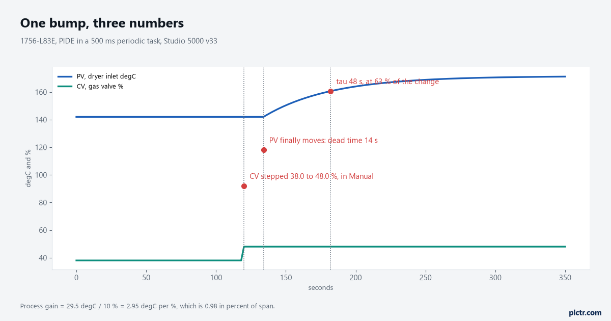
Everything you need is on this one chart. The flat bit after the step is dead time, the curve’s shape is the time constant, and the height of the whole move divided by the height of the step is the process gain.
The loop above is a dryer inlet air temperature on a 1756-L83E, PV span 0 to 300 degC, gas valve 0 to 100%, PIDE in a 500 ms periodic task. It sat at 38.0% and 142.0 degC. Step the output to 48.0% and leave it alone.
Three numbers come off that.
Dead time, 14 seconds. The gap between the step and the first movement of PV. This is the number that decides how aggressive you are allowed to be, and it is the one people forget to measure because nothing appears to be happening while it elapses.
Time constant, 48 seconds. The time from first movement to 63% of the total change. PV went from 142.0 to 171.5, so 63% of 29.5 degC is 18.6 degC, which lands at 160.6 degC, which the trend crosses 48 seconds after the PV started to move.
Process gain, 2.95 degC per percent. The 29.5 degC of PV change divided by the 10% of CV change. Because PIDE thinks in percent of span, convert it: 29.5 degC on a 300 degC span is 9.83% of span, against a 10% step, so the gain PIDE cares about is 0.98 and is very nearly dimensionless.
Now pick a tuning rule. This part is engineering judgement rather than anything Rockwell publishes, and it should be labelled as such — the PIDE manual documents parameters and equations, not tuning rules. A lambda-style PI calculation with the closed-loop time constant set equal to the open-loop one gives controller gain Kc = tau / (Kp x (lambda + theta)) = 48 / (0.98 x 62) = 0.79, and reset time Ti = tau = 48 seconds. Derivative zero, because this is a temperature loop with real dead time and derivative on dead time is a way to amplify noise.
Kc 0.79, Ti 48 seconds, Td 0. Those are the gains. Now write them down in the right units.
Same tuning, four different numbers
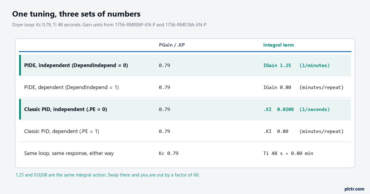
The two highlighted rows are both called independent, and the integral number differs by sixty because one manual counts in minutes and the other counts in seconds.
Set DependIndepend and it changes what IGain means, not just how it is scaled. In the dependent form, the manual says, you enter the integral time constant in units of minutes/repeat, and it adds the useful plain-English gloss: it takes TI minutes for the integral term to repeat the action of the proportional term in response to a step change in error. Larger is slower. In the independent form you enter the integral gain in units of 1/minutes, and larger is faster.
Same parameter, same tag, opposite direction. That inversion is why tuning constants carried across from a DCS that works in minutes per repeat are so dangerous typed into a PIDE left on its independent default. A number chosen to give slow integral action now gives fast integral action, and on a dryer you find out in a few minutes. On something with real mass you find out when it overshoots through an interlock. DGain is less exciting but worth the same check: independent form is derivative gain in minutes, dependent form is derivative time constant in minutes, and at least those two share a unit. The classic PID instruction is where the sixty comes in. 1756-RM018A’s setup table for .KI reads, for independent gains, integral gain in 1/sec; for dependent gains, reset time in minutes per repeat. Its variable list for the independent equation says the same thing a second way, integral gain in seconds to the minus one. So the dependent columns of the two instructions agree with each other in minutes per repeat, and the independent columns do not agree at all.
If you remember one thing from this page, remember that the dependent form is the portable one.
Autotune, and what it will not do for you
PIDE has a built-in autotuner and it is better than its reputation.
Three caveats decide whether you can use it at all.
It is an open-loop autotuner, which the manual states directly, so it does what you were about to do by hand: it steps the output and watches. It needs an activation key — the autotuner is installed with the Logix Designer application but you need that key to enable it, which is a purchasing conversation rather than a technical one, and it is the reason the Autotune tab is greyed out on most machines people meet. And it is function block only. The manual says it is not available in ladder diagram or structured text programming. A PIDE called from Structured Text is a perfectly legal PIDE, and it cannot be autotuned.
You give it a tag of type PIDE_AUTOTUNE on the Autotune tab, and drive it through AtuneAcquire, AtuneStart, AtuneUseGains, AtuneAbort and AtuneUnacquire, which means an operator interface can run the whole sequence without Studio 5000 present.
Do the manual bump anyway, at least once per plant.
Not because the autotuner is wrong, but because the three numbers are yours after that and the gains are not. Dead time of 14 seconds tells you what any loop on that dryer can achieve, tells you whether a 500 ms task was ever necessary, and tells the next person why the gains are what they are. An autotuner hands you three gains and no understanding of the process behind them, and six months later nobody can say whether a loop that has started hunting has drifted or was always marginal.
When the period of the oscillation is the clue
A loop that hunts is usually a gains problem. Sometimes it is not, and the period tells you which.
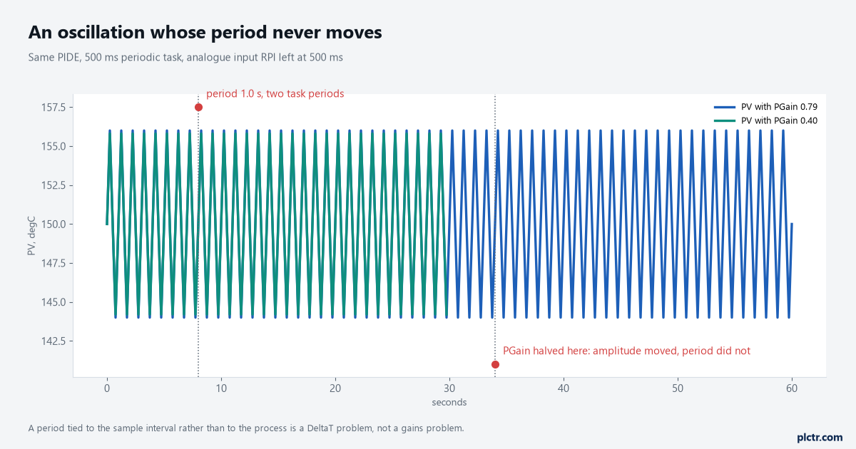
Halve the proportional gain and a gains problem changes period. This one did not, which points at the sample interval rather than at the tuning.
Here is the diagnostic. Halve PGain and watch what happens to the oscillation. If the period stretches or the hunting stops, you were too aggressive and the answer is in the gains. If the amplitude shrinks a bit and the period does not move at all, the period is being set by something other than the process, and on a PIDE that something is almost always the sample interval.
So go and look at the analogue input’s RPI against the task period. The manual’s rule was 5 to 10 times faster than the task executes, and an input module left at an RPI equal to the task period fails that by an order of magnitude. The block is then differencing a staircase rather than a signal, and the first thing to suffer is derivative action, which is one reason DGain at zero is a sensible starting point rather than a cop-out. Two other things produce the same signature and are worth eliminating in the same visit. A PIDE in a continuous task has a DeltaT that moves with controller load, which is the varying-DeltaT discontinuity the manual warns about rather than a tuning fault, and the fix is a periodic task rather than smaller gains. And an analogue module’s own filter can be slower than the loop: a 1756-IF8 on its default 60 Hz module filter has a minimum real-time sample of 88 ms in single-ended wiring, so asking for a 50 ms RPI on that channel gets you the same number twice as often rather than a fresher number.
Neither of those is fixed by touching a gain, and both look exactly like a badly tuned loop from the faceplate.
What to check next
Put PV, CV and SP on one trend at the task rate before you change anything, and do the gain-halving test above. It takes four minutes and it tells you whether you are in a tuning problem or a sampling problem, which are two different afternoons. If it is a tuning problem, do the bump properly and write the three numbers on the loop sheet rather than only the gains — the gains are derived, the process is not. The trend tool itself is covered in PLC trend chart settings and monitoring, the wider setup from an empty project through to a working faceplate is in PLC PID control: set up and tune a loop in Studio 5000, and if the task period itself is the thing in question, measuring it properly comes first in PLC scan time and cycle time.