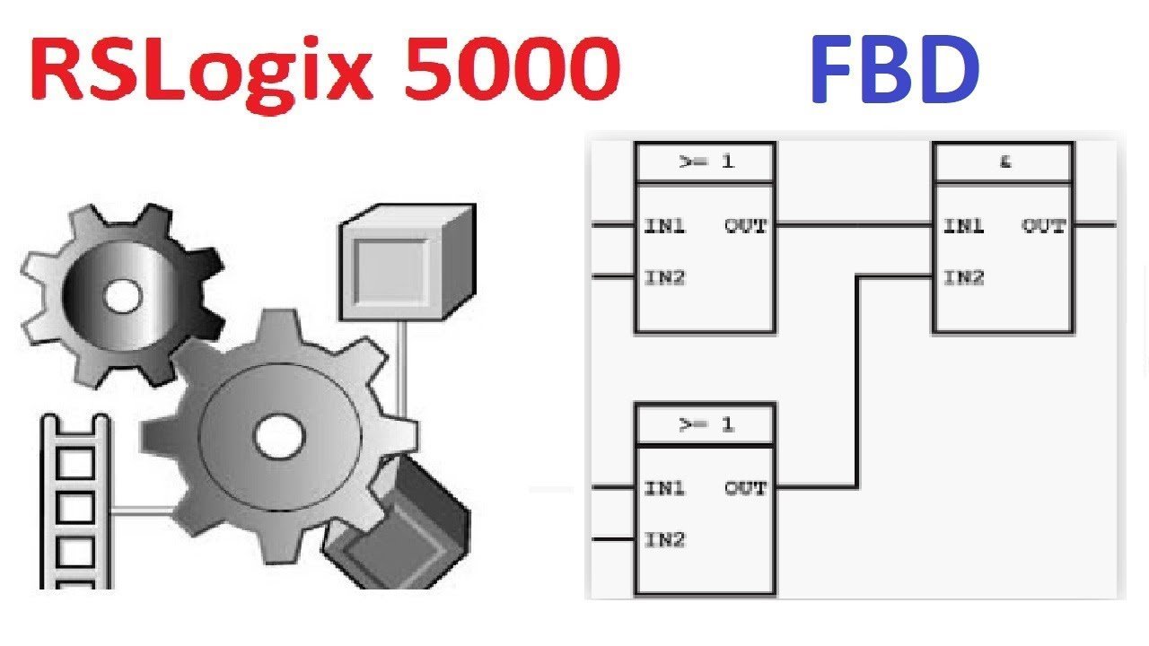
A function block routine that verified fine last week now has a question mark on four blocks and will not download. Or worse, it downloads, runs, and one value on the HMI is always one scan behind the others.
Nobody moved a block. Somebody added a wire.
Execution order in FBD has nothing to do with where a block sits. Publication 1756-PM009J-EN-P, March 2022, is explicit: sheets “do not affect the order in which the function blocks execute”. Order comes from the wiring.
“1. The controller latches all data values in IREFs. 2. The controller executes the other function blocks in the order determined by how they are wired. 3. The controller writes outputs in OREFs.”
Those three lines explain most of the surprises this language has to offer.
Why dragging the block did not help
Because position is decoration. All sheets execute, every scan, in an order the compiler works out from the wires. The manual’s advice on sheets is organisational: use one sheet per device, a motor or a valve, so a human can find things. Which means the first instinct, dragging a block above another one so that it runs first, does nothing at all. It is the single most common wasted half hour in FBD, and it looks like it should work because that is exactly how a ladder rung behaves.
If you want block 1 to run before block 3, wire block 1’s output into block 3’s input. That is the only lever there is.
The question mark, and the arrow that clears it
When blocks form a loop, “the controller cannot determine which block to execute first, and it cannot resolve the loop”.
Every block in the loop gets marked, and nothing verifies until you say where to break the circle.
The fix is the Assume Data Available indicator, the little arrow on a wire. Right-click the feedback wire, the one closing the loop, and mark it. The manual’s description of what that means is worth quoting because it is the whole mechanism: “The arrow indicates that the data serves as input to the first block in the loop.” The marked wire carries the value produced on the previous execution of the routine.
Three rules govern it. Two of them are the ways people get it wrong.
| Rule | What happens if you break it |
|---|---|
| Mark the wire that creates the loop, the feedback wire. | This is the correct move. The block fed by that wire executes first, using last scan’s value. |
| Do not mark all the wires of a loop. | The manual shows this as the “not OK” case: with every wire marked the controller still cannot resolve the loop, because nothing tells it where the loop starts. Marking more wires feels like it should help more. It helps less. |
| When two or more wires connect the same pair of blocks, use the same indicator on all of them. | Also shown as “not OK”. One wire marked and one not is the case that verifies inconsistently and is miserable to spot, because visually the two wires sit on top of each other. |
The same indicator is the documented way to create a deliberate one scan delay between two blocks.
Mark the wire, and block 1 executes first using the output block 2 produced on the previous scan.
Which is also where that one-scan-stale HMI value came from. Somebody marked a wire to clear a question mark and inherited a delay nobody asked for.
IREFs are latched, and this changes what your logic means
“The controller latches all data values in IREFs” at the start of the routine. Every IREF referencing a given tag in that routine uses the same latched value, for the whole scan of that routine. So if something inside the routine writes to that tag, no IREF in the same routine sees the new value. Not the one three blocks downstream, not the one on another sheet. They all carry the value from the top of the scan, and the change shows up next time round.
This is not a defect. It is what makes execution order safe to reason about at all.
But a habit carried over from ladder, where a rung reads whatever the rung above just wrote, produces code that reads correctly and runs one scan late.
What an unexecuted block does with its outputs
Every process instruction has an EnableIn, and the execution tables in 1756-RM006P-EN-P, September 2025, are consistent about it. With Tag.EnableIn true, “EnableIn and EnableOut bits are set to true. The instruction executes.” With Tag.EnableIn false, “EnableIn and EnableOut bits are cleared to false.” Read that second line carefully. It says the two enable bits are cleared. It says nothing about the instruction’s other outputs, because there is nothing to say: the instruction did not execute, so nothing recalculated them. They hold.
That is what catches people coming from ladder, where dropping a rung false visibly de-energises the output.
Drop EnableIn on a totalizer and the Total does not go to zero. It stops moving.
Functions are not function blocks
Newer versions give you Functions alongside Function Blocks. Functions “do not require backing tags, require less memory than function blocks, sometimes execute more quickly, and use less space in a function block diagram.” The catch is availability, and the manual states it precisely: “Functions are available only in Logix Designer versions 32 and later on CompactLogix 5380, CompactLogix 5480, ControlLogix 5580, Compact GuardLogix 5380, and GuardLogix 5580 controllers.” Which means a routine written with Functions will not open on a ControlLogix 5570, and a colleague still on v31 cannot help you with it, so it is worth deciding deliberately rather than discovering it during a breakdown.
Where FBD actually earns its place
Analog loops. This is not a matter of taste. A PIDE with its alarms, its ramp and its select block wired together reads like the P&ID it came from, and the same arrangement in ladder is a column of instructions with the signal path held in your head. And the PIDE carries the one FBD trap that will genuinely wreck a process rather than merely annoy an engineer, which is the gain form.
| Parameter | Independent Gains form | Dependent Gains form |
|---|---|---|
| PGain | Unitless proportional gain. Affects the proportional term only. | Unitless controller gain. Changing it moves all three terms together. |
| IGain | Integral gain in units of 1/minutes. A larger value gives a faster integral response. | Integral time constant in units of minutes/repeat. A larger value gives a slower integral response. |
| DGain | Derivative gain in units of minutes. | Derivative time constant in units of minutes. |
| DependIndepend | False. This is the default. | True. |
Look at what IGain does across those two columns. Same parameter, same tag, and the effect of increasing it is inverted, because in one form it is a gain and in the other it is a time constant. Take tuning constants off a DCS that works in minutes per repeat, type them into a PIDE left at its default independent form, and a number chosen to give a slow integral action now gives a fast one. On a temperature loop you find out within the hour. On something with real inertia you find out when it overshoots.
The algorithm is a velocity form, “similar to that used in most DCS systems”.
CalculatedCV is built from CVn-1 plus the changes in the three terms rather than recomputed from scratch, which is why gains can be changed on the fly without bumping the output.
Getting the sample time right
The timing modes apply to fourteen instructions, PIDE, TOT, INTG, LPF, NTCH, RLIM, SCRV and the rest of the time-based family, and there are three of them.
| TimingMode | Where DeltaT comes from | When to pick it |
|---|---|---|
| 0, Periodic | In a periodic task, the period of the task. In an event or continuous task, the elapsed time since the previous execution, truncated to whole milliseconds, so an actual 10.5 ms becomes a DeltaT of 10 ms. | The default, and the manual’s recommendation for most control applications. Put the routine in a periodic task and DeltaT stops being something you think about. That truncation on its own is reason enough not to run loops in a continuous task. |
| 1, Oversample | Whatever value is written into the OversampleDT parameter. | When you are controlling execution yourself, for instance gating EnableIn with a timer. The manual points you at real time sampling instead if the process input carries a time stamp. |
| 2, Real time sampling | The difference between two time stamp values read from the tag named in RTSTimeStamp, normally a parameter on the input module itself. | When the input has a time stamp and you need precise coordination. The instruction compares the configured RTSTime against the calculated DeltaT, and “if DeltaT is not within 1 millisecond of the configuration time, the instruction sets the RTSMissed status bit”. |
RTSMissed is your evidence that the loop is not seeing every update.
One piece of guidance covers all three modes, and the manual states it twice: “The update of the process input needs to be synchronized with the execution of the task or sampled 5-10 times faster than the task executes in order to minimize the sampling error between the input and the instruction.”
Five to ten times faster. A PIDE in a 100 ms periodic task wants its analog input arriving every 10 to 20 ms.
An RPI left at whatever the module defaulted to is how a loop ends up hunting for reasons that look like tuning and are not.
The argument about maintenance
The honest objection to FBD is not technical. It is that the person called out at 2am is more likely to read ladder fluently, and a diagram whose execution order is invisible is harder to reason about under pressure than a rung you can trace left to right. That objection is strongest exactly where FBD is weakest, which is discrete logic: interlocks, permissives, start and stop sequences. Those belong in ladder, and putting them in FBD for the sake of consistency buys consistency at the price of everything else.
It is weakest where FBD is strongest. Nobody troubleshoots a cascade loop faster in ladder.
Split the project rather than picking a winner. Discrete in ladder, loops and analog conditioning in FBD, sequencing in SFC or Structured Text where it earns its place.
The maintenance argument mostly evaporates once the FBD is confined to the part of the machine nobody was going to trace by eye anyway.
Frequently asked
Can I force a block to run first?
Only by wiring. Position on the sheet, sheet order and the order you created the blocks in all have no effect.
What does the question mark on a block mean?
It is in an unresolved loop. Mark the feedback wire with Assume Data Available, and mark only that wire.
When is order recalculated?
On verifying a routine, verifying a project that contains an FBD routine, and downloading a project that contains one.
How do I get data to another sheet?
An OCON and a matching ICON. Each OCON needs a unique name, and several ICONs can reference one OCON when the same value is wanted in several places.
Which gain form should I use?
Whichever matches the numbers you already have. If the site’s records are in minutes per repeat, set DependIndepend true and keep them.
Next step
Open your worst-behaved FBD routine and check two things before anything else: which wires carry an Assume Data Available arrow, and whether any tag written inside the routine is also read by an IREF in the same routine. Those two account for most of the “it works but the number is wrong” reports. Background on the language itself is in the PLC function block diagram introduction and introduction to PLC programming languages. For the loop side, see implementing PID control in PLC systems and the ALMA analog alarm block. Task periods and why they matter are in PLC scan time and cycle time.
Primary sources: Rockwell Automation, Logix 5000 Controllers Function Block Diagram, publication 1756-PM009J-EN-P, March 2022; Rockwell Automation, Logix 5000 Controllers Process Control and Drives Instructions, publication 1756-RM006P-EN-P, September 2025, chapters 1 and 9.