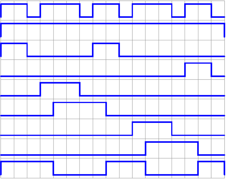
An eight-station rotary indexer on a 5069-L330ER. An SQO drives the station outputs, and on the first false-to-true transition the outputs light station one. Not station zero. Station zero never fires at all, and the operator wants to know why the first pot off the carousel is empty.
That is not a bug in your logic. Straight out of publication 1756-RM018A-EN-P, September 2025: “When .EN transitions from false to true, the .POS is incremented.” Incremented first, transfer second. Element 0 is a parking space, not a step.
What SQO actually does on the transition
Three things happen, in this order. The position increments. If the new .POS has reached or passed .LEN it wraps back to 1, never to 0. Then the data moves, and the way it moves is the part everybody skims: the Array element at .POS is ANDed with the Mask, the current Destination value is ANDed with the complement of the Mask, and the two results are ORed together before the answer goes back into the Destination. Two of those three operations involve the mask, which should tell you how much of the instruction’s behaviour the mask actually controls.
Most sequencer problems are mask problems wearing a different hat.
The mask, worked through with real numbers
Rockwell’s own SLC example in 1747-RM001G-EN-P spells this out better than any explanation does. File #B10:1, Mask 0F0F, Dest O:14.0, Control R6:20, Length 4, Position 2.
Sequencer file #B10:1, step 2      1111 0101 0100 1010
Mask                    0F0F       0000 1111 0000 1111
                                   -------------------
step AND mask                      0000 0101 0000 1010

Destination O:14.0 before          0000 0101 0000 1010
Complement of mask      F0F0       1111 0000 1111 0000
                                   -------------------
dest AND NOT mask                  0000 0000 0000 0000

OR the two halves                  0000 0101 0000 1010
Outputs 01 and 03 on the O:14 card turn on, and so do 08 and 10. Nothing else does. That is the whole point of the mask: bits 4 to 7 and bits 12 to 15 were blocked, so whatever other logic owns them keeps the value it had. In Logix the same mask is written 16#0F0F, and the arithmetic is identical except that the array element is 32 bits wide, so the complement the instruction uses is 16#FFFFF0F0 rather than 16#F0F0. That difference is not cosmetic. The top sixteen bits of a Logix destination are protected by a 16-bit mask, not exposed by it. The SLC manual puts it as “the bits mask data when reset and pass data when set”, and on Logix the Mask operand description says the same in different words: which bits to block, meaning 0, or pass, meaning 1.
Get the mask too wide and there is no error. Just a sequencer stamping zeroes over somebody else’s outputs on every step, reported as an intermittent fault by somebody who has no idea the sequencer exists.
Nothing in the software will warn you.
A mask entered as a hex code is fixed. Enter an element or file address instead and the mask becomes variable, changing with each step. Few applications need that, but it is worth knowing before you decide a sequencer cannot do what you want.
Position 0 is where the two generations disagree
This is the section worth reading twice, because the answer genuinely differs depending on what is in the panel.
On Logix the Position operand reads “Current position in the array. Initial value is typically 0.” The instruction increments before it transfers, so in normal cyclic running element 0 is never written to the Destination at all, and the only way back to it is to clear the control structure, which Rockwell’s own example does with a RES instruction conditioned on the first-scan bit. Note what that means for a machine that has been running for a year: nothing in the program has looked at element 0 since the last power cycle, so an error in it will sit there undetected until the day somebody resets the sequencer and the machine does something nobody has seen before.
On an SLC 500 or a MicroLogix the older manual is blunter. “Length is the number of steps of the sequencer file starting at position 1. The maximum number you can enter is 255 words. Position 0 is the startup position.” Same idea. Then it adds an edge case I have not found stated anywhere in the Logix documentation:
“If the position is equal to zero at startup, when you switch the processor from the program mode to the run mode instruction operation depends on whether the rung is true or false on the first scan. If true, the instruction transfers the value in step zero. If false, the instruction waits for the first rung transition from false-to-true and transfers the value in step one.”
So on an SLC, step zero can fire. Only when .POS happens to be 0 and the rung happens to already be true the moment you go to Run. A machine power-cycled with a permissive already made will pulse a step nobody wrote logic for. The same machine stopped properly will not.
If you have ever chased an output that flicks once on power-up about one restart in ten, and never while you are watching, that is a candidate. It is also why “only on a Monday” is sometimes a real diagnosis: Monday follows the only proper shutdown of the week.
Set the position deliberately on first scan and the whole class of problem disappears.
One SLC allocation detail bites people: the file address you give the instruction is step zero, and sequencer instructions use length plus one word for each file referenced. A length of 16 needs 17 words. Same rule for source, mask and destination when they are addressed as files.
The operands, side by side
Worth having in one place, because the three instructions look interchangeable and are not. Descriptions here follow the operand tables in chapter 10 of 1756-RM018A-EN-P.
| Operand | Type and format | SQI | SQL | SQO |
|---|---|---|---|---|
| Array | DINT array tag | The sequencer array. Give it the first element of the array, and do not use CONTROL.POS in the subscript. This note appears identically on all three instructions, which suggests Rockwell has been answering the same support call for a long time. | ||
| Mask | SINT, INT or DINT, tag or immediate | Applied to both the Source and the Array element at .POS before the two are compared. Anything narrower than a DINT is zero extended to DINT width first. | Not used | Determines which bits to block, meaning 0, or pass, meaning 1, during the output masking operation. |
| Source | SINT, INT or DINT, tag or immediate | The input data compared against the array element at .POS. | The data loaded into the array at the position .POS points to. | Not used |
| Destination | DINT tag | Not used | Not used | Output data from the sequencer array. This is the value that goes through the output masking operation, and it is read as well as written, because the complemented mask preserves the bits the sequencer does not own. |
| Control | CONTROL tag | The control structure. Every one of the three says to use the same tag as the other two, and sharing it is what ties the stepping to the testing. | ||
| Length | DINT immediate | Represents the CONTROL structure .LEN. | Represents .LEN. | The number of elements in the array to output. |
| Position | DINT immediate | Represents .POS. | Represents .POS. | Current position in the array. Initial value is typically 0. |
The control structures, and how much they differ
SQO and SQL get five CONTROL members on Logix. SQI gets three.
| Member | SQO | SQL | SQI |
|---|---|---|---|
| .EN | Instruction is enabled. Set true during prescan, cleared when rung-condition-in is false. | Instruction is enabled. | Not listed |
| .DN | Set when .POS = .LEN | Set when all the specified elements have been loaded into Array | Not listed |
| .ER | Instruction encountered an error | Set when .LEN is less than or equal to 0, .POS is less than 0, or .POS is greater than .LEN | Instruction encountered an error |
| .LEN | Number of sequencer steps in the array | ||
| .POS | Array element used in the output masking operation | Where in the Array the Source value will be stored | Array element being compared with the Source |
There is no .UL member on any of them. That bit belongs to FFU and LFU, the unload instructions.
SQL is the only one with its own documented major fault: type 4, code 20 when position exceeds the size of Array. SQI and SQO say “none specific to this instruction” and send you to Common Attributes, where an out-of-range subscript is the same type 4, code 20.
Which means a sequencer major fault almost always reads as type 4, code 20.
The SLC control is three words rather than a structure. Word 0 holds the status bits, word 1 the length, word 2 the position, and the bits sit at fixed positions: FD at bit 08 and only on SQC, ER at bit 11, DN at bit 13, EN at bit 15. That error bit is harsher than the Logix equivalent, and it is worth knowing why. ER is set when the processor detects a negative position value, or a negative or zero length value, and the manual states plainly that this results in a major error if it is not cleared before the END or TND instruction runs. A length of zero is not quietly ignored. It stops the processor.
On Logix, SQL sets .ER for the same condition and the manual stops there.
Four things the manual tells you not to do
Do not put CONTROL.POS in the Array subscript. All three operand tables say so. Give the instruction the first element and let it do the indexing. Writing Steps[SqoControl.POS] makes the rung evaluate a subscript, then the instruction indexes again from there.
Do not expect a sequencer in a safety routine. The pseudo-operand table in chapter 20 lists all three with LEN and POS as pseudo-operands, and in the last column, “Allowed in safety routines: No”.
Do not expect SQI to step anything. “If you use the SQI instruction without a paired SQO instruction, you have to externally increment the sequencer array.” SQI ANDs the array element at .POS with the Mask, ANDs the Source with the same Mask, compares, and sets rung-condition-out true when they match. That is the whole instruction. Rockwell’s worked alternative uses an ADD to increment, a GRT to decide whether another value is available, and a MOV to reset the position after a full pass.
Do not mix widths carelessly. The Array operand is a DINT array. Mask and Source take SINT, INT or DINT, as a tag or as an immediate, while Length and Position are documented as DINT immediates. Anything narrower than a DINT is zero extended to DINT width before it is used, which sounds harmless and is not: a 16-bit mask against a 32-bit array element leaves the top sixteen mask bits as zeroes, and zero blocks. Bits 16 to 31 of your destination will never change no matter what you put in the array.
The applicability note covers CompactLogix 5370 and 5380, ControlLogix 5570, 5580 and 5590, the GuardLogix equivalents, and older platforms such as the 1769-L30ER.
A sequencer table somebody else can read
The hardest part of maintaining another engineer’s sequencer is that the array shows up as a column of decimal numbers. Set the array’s display style to binary in the tag editor, and comment the tag with the bit map, because nobody is going to work out that 3084 means stations 2, 3, 11 at two in the morning, and the person who has to work it out will be doing so with a torch in their teeth while somebody senior asks how long it is going to take.
Binary display costs nothing and it is the single best thing you can do for whoever inherits the machine.
The tag setup for that indexer: Steps as a DINT[9], SqoControl as a CONTROL with .LEN of 8, and a Mask of 16#00FF, because bits 8 to 31 of the destination belong to the manual jog logic and the sequencer has no business touching them.
| Element | Value, bits 7 to 0 | What the step does |
|---|---|---|
| 0 | 2#0000_0000 | Park position. Never transferred while the machine is cycling, which is exactly why it is the one element nobody checks. |
| 1 | 2#0000_0011 | Infeed clamp closes and the index motor runs. |
| 2 | 2#0000_0110 | Index motor runs and station 1 fills. |
| 3 | 2#0000_0100 | Index motor only. The dwell steps are what give the fill valve time to close before the table moves. |
| 4 | 2#0001_0100 | Index motor runs and station 2 caps. |
| 5 | 2#0000_0100 | Index motor only. |
| 6 | 2#0010_0100 | Index motor runs and the reject blow-off fires. |
| 7 | 2#0000_0100 | Index motor only. |
| 8 | 2#1000_0000 | Cycle complete pulse, which is what the SQI upstream is comparing against. |
With .LEN of 8, .POS reaches 8, .DN sets, and the next transition wraps .POS to 1.
When a sequencer is the wrong tool
What follows is judgement rather than documentation, so weigh it accordingly.
A sequencer earns its place when the pattern of bits is fixed, the step count is stable, and the people maintaining it will read a table rather than read logic. Bottling indexers and wash cycles fit that shape. So do traffic signals, and a nine-element array beats eight rungs of latches.
It stops earning its place the moment the sequence branches. A step that can go to one of three places next, a step waiting on two different permissives, a step that needs a name on an HMI rather than a number: all of that fights the instruction, and the workarounds get ugly fast. A DINT holding a state number, a CASE statement or a set of equality-driven rungs, and a UDT array holding the step data will give you named steps and arbitrary transitions, and a fault display that can show a step in words instead of showing 6. You lose the compactness. You gain the ability to explain the machine to somebody over the phone at 3am, which on most days is worth more.
The argument that sequencers are obsolete still goes too far. Rewriting a working SQO as forty rungs of state logic is not an improvement anybody thanks you for.
What goes wrong, and what it looks like
The first station never fires. Element 0 was written as step one, so everything is shifted by one for the life of the machine, and the cycle appears to have a dead step at the end as well. Move the data up one element and set .LEN to the number of real steps.
The sequencer resets to step one, not step zero. It is meant to. A genuine return to the park position needs a RES on the control tag, usually conditioned on the first-scan bit.
Outputs that are not part of the sequence keep dropping out. The mask is too wide. Narrow it to the bits the sequencer owns and the complemented-mask half of the operation protects the rest.
The position is wrong after a download. .POS is a normal DINT in a normal tag, holding whatever it held. Decide whether the machine resumes where it was or parks, then write the logic that enforces it.
Frequently asked
Can the sequencer array be an INT array?
On Logix the Array operand is documented as DINT. Mask, Source and Position take SINT, INT or DINT.
How many steps can a sequencer have?
The SLC 500 manual gives a hard limit of 255 words. The current Logix manual states no ceiling in the sequencer chapter, so treat it as bounded by your array rather than quoting a number you cannot source.
What sets the done bit?
On SQO, when .POS equals .LEN. On SQL, when all the specified elements have been loaded. On the SLC, after the instruction has operated on the last word in the file, reset on the next false-to-true transition after the rung goes false.
Do the three instructions share a control tag?
They are meant to. Sharing the CONTROL structure is what makes the SQO step the position the SQI is testing against.
Next step
Before writing a rung, open the tag editor, build the array and fill in the bit pattern for every element including element 0. If the table does not make sense as a table, the sequencer is the wrong instruction and you found that out for ten minutes. The indexing behind all of this is the same mechanism covered in PLC indirect addressing, the CONTROL structure is shared with the FIFO instructions in FFL and FIFO usage, and if the sequence turns out to branch, sequential function charts are built for that shape. Timing between steps is in timer and counter instructions. For the same step logic repeated at fourteen stations with a takt to hold, see assembly line station logic.
Primary sources: Rockwell Automation, Logix 5000 Controllers General Instructions, publication 1756-RM018A-EN-P, September 2025, chapter 10 and chapter 20; Rockwell Automation, SLC 500 Instruction Set Reference Manual, publication 1747-RM001G-EN-P, November 2008, chapter 7.