The ladder execution table for a TON in 1756-RM018A lists four things that happen when its rung goes false: .EN cleared, .TT cleared, .DN cleared, .ACC cleared to zero. The table for an RTO, same condition, same page layout, lists two. .EN and .TT. That missing pair is the entire definition of retentive, and TON vs RTO comes down to those two lines.
So the short answer, before any of the reasoning.
Use a TON when the delay has to restart from nothing every time the condition drops, which is nearly every motor start interlock you will ever write. Use an RTO when you are accumulating something across interruptions, like run hours or total fault dwell. Use a TOF when you want something to keep running for a while after the condition goes away. And know that retentive on a Logix controller means retained through the rung and through a mode change, and means nothing whatsoever about a power cycle.
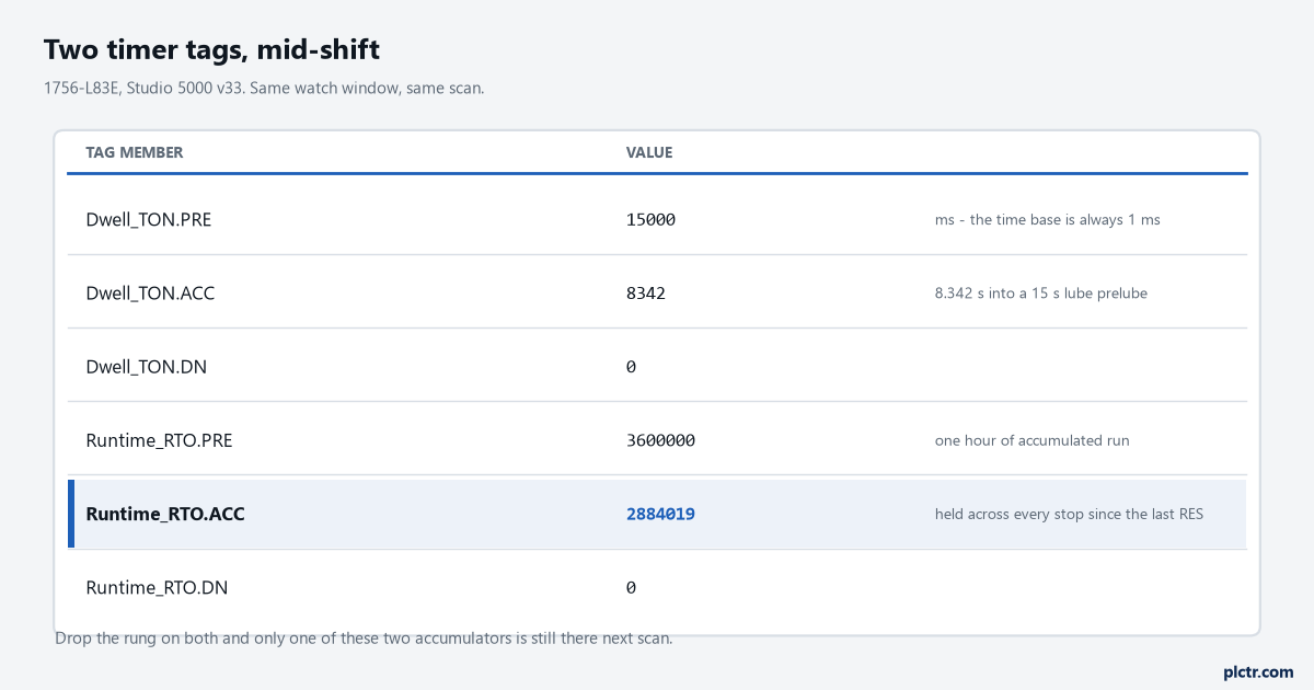
The RTO’s 2,884,019 ms did not arrive in one stretch. It is the sum of every period the rung was true since somebody last reset it, which may have been at commissioning.
The three timers, and the job each is actually for
A 15 second prelube before the main drive is allowed to start is a TON. If the permissive drops at second 12, you want the full 15 again, not 3. Total running hours on that same drive is an RTO, because the motor stops forty times a shift and the number has to keep going up regardless. A fan that must keep turning for 90 seconds after the burner shuts off is a TOF, which times while its rung is false rather than while it is true, and hands you a .DN bit that is already true before anything has happened. That inversion catches people once and then never again, and the reason it is worth the single confusion is that the alternative — a TON started by a falling edge, seal-in, reset — is four rungs of logic to reproduce one instruction badly.
| Instruction | Times while | .ACC on rung false | Needs a RES |
|---|---|---|---|
| TON | rung true | cleared to zero | no |
| TOF | rung false | see below | no |
| RTO | rung true | held | yes |
Presets are in milliseconds. Always.
The time base is always 1 millisecond, so a 15 second preset is .PRE of 15000 and a one hour preset is 3600000. There is no time-base dropdown to get wrong, which is one of the few things Logix made simpler than the platforms it replaced. .PRE and .ACC are DINT, and a negative value in either is a major fault, type 4 code 34 — worth knowing because that is how a bad indirect index into a timer array announces itself, loudly, rather than by quietly timing the wrong thing. On a CompactLogix 5380, ControlLogix 5580 or ControlLogix 5590 you also get the TIMER_T structure, where .PRE and .ACC are the TIME type and carry microsecond fidelity. Same instructions, finer resolution, different data type on the tag, and that last part is the one that bites when you export a routine from a 5580 and import it into a 5570 project.
TON vs RTO: what retentive covers, and what it quietly does not
Put the two execution tables side by side and the argument settles itself.
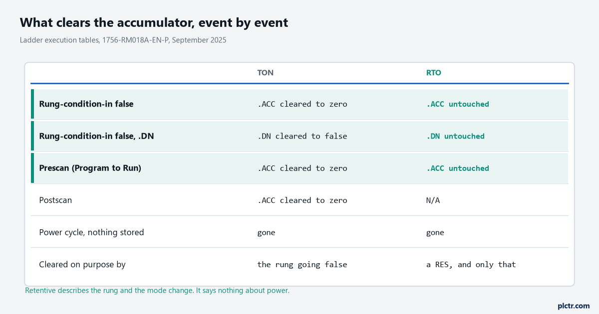
The three highlighted rows are what retentive buys you. The row below them is what people assume it buys and it does not.
Three things are worth pulling out of that, and the first one is not the accumulator.
The first is .DN, and it is the half of this that nobody quotes. Everybody knows an RTO holds its accumulator. Rather fewer notice that the execution table does not clear .DN either, so an RTO that reached its preset stays done after its rung drops, and stays done through a transition to Program and back, and stays done through the Clear Majors that somebody hits at three in the morning. A sequence that latches on RTO.DN
.EN and .TT. Go to Program, go back to Run, and every TON in the project is sitting at zero while every RTO is exactly where you left it.The third one is the one people get wrong, and it deserves its own heading.
A power cycle is not a mode change
There is no per-tag retain switch on a Logix controller. Nothing in the timer instruction decides this, and the RTO’s retentive behaviour stops dead at the power supply.
What happens instead depends on the controller family and on one dropdown.
Those two do not agree with each other.
Every current Logix controller has an energy store of some kind — a removable 1756-ESMCAP on a 1756-L7x, an embedded circuit on the 1756-L8x and the CompactLogix 5380, reported through the EnergyStorageStatus diagnostic and a CHRG message while it charges. What that store is for is finishing the job after the volts go away, and the manuals are not identical about how much of the job. 1756-UM001Q describes the ESM’s role on a 5570 as providing power to save the program to onboard nonvolatile storage, and 1756-UM543T’s status message on a 5580 uses the same word: “the embedded storage circuit does not have sufficient energy to enable the controller to save the program if a powerdown occurs”. 1769-UM021K, covering CompactLogix 5370, is broader and says the ESM allows the controller to write customer application and tag data to onboard nonvolatile memory. Different families, different published scope, and the one thing none of them promises is that a specific accumulator will be where you left it.
Then the dropdown overrules all of it.
1756-PM017J, the nonvolatile memory card manual, gives three Load Image settings — On Power Up, On Corrupt Memory, and User Initiated — and attaches one sentence that decides this argument: during a power cycle, online changes, tag values and network schedules that you have not stored on the memory card are lost. If the card is set to load On Power Up, the controller reloads the stored project every time it comes back, and the stored project’s tag values are the ones you get. That is a restore point rather than retention, and it fails in the more dangerous direction: an accumulator that goes to zero is obviously wrong, while one that quietly reverts to the 41 hours it held when somebody pressed Store at commissioning is not.
So the honest answer for run hours on a machine that loses power is that the controller will not do this for you. Write the number somewhere that survives, on a schedule you chose: a MSG to a historian, a value the HMI owns and writes back on startup, a deliberate periodic store. The RTO accumulates between those writes. It does not replace them.
The RES that people forget, and the one you cannot use
An RTO with no reset anywhere in the project works beautifully for exactly one cycle.
The RES instruction clears .ACC
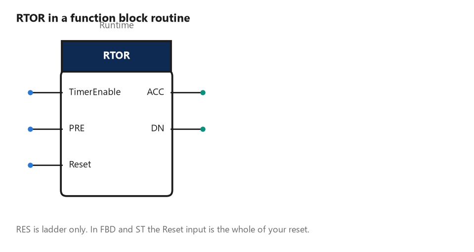
The function block cousin carries its own Reset pin, which is the answer in FBD and ST. RTOR accumulates until it goes false, retains .ACC, and clears only when you drive that input.
RTOR is the instruction you want instead.
Its documentation is unusually direct about the contract: it accumulates time until it is false, it retains its .ACC value when false, and you must clear .ACC using the Reset input. No ambiguity, no RES required, and the Reset pin is visible on the block so the reviewer can see whether it is wired. That last property is the real argument for FBD here. A missing RES in ladder is an absence, and absences do not show up on a printout; an unwired Reset pin is a dangling input. While we are on properties that look like bugs, there is one more worth knowing about both TON and RTO: when the timer is enabled, timing can be paused by setting .DN to true, and resumed by clearing .DN to false. That is documented behaviour rather than an accident. So if anything else in your program writes to that bit — an HMI button bound one tag along, a COP that lands across a timer array, an AOI that takes the timer as an InOut and gets tidy with it — your timer stops counting while its rung sits there happily true and every contact on the screen is green.
The timer that never times out
Preset 6000 ms. The rung is true. The .ACC never gets past about 4000 and the .DN bit never comes on.
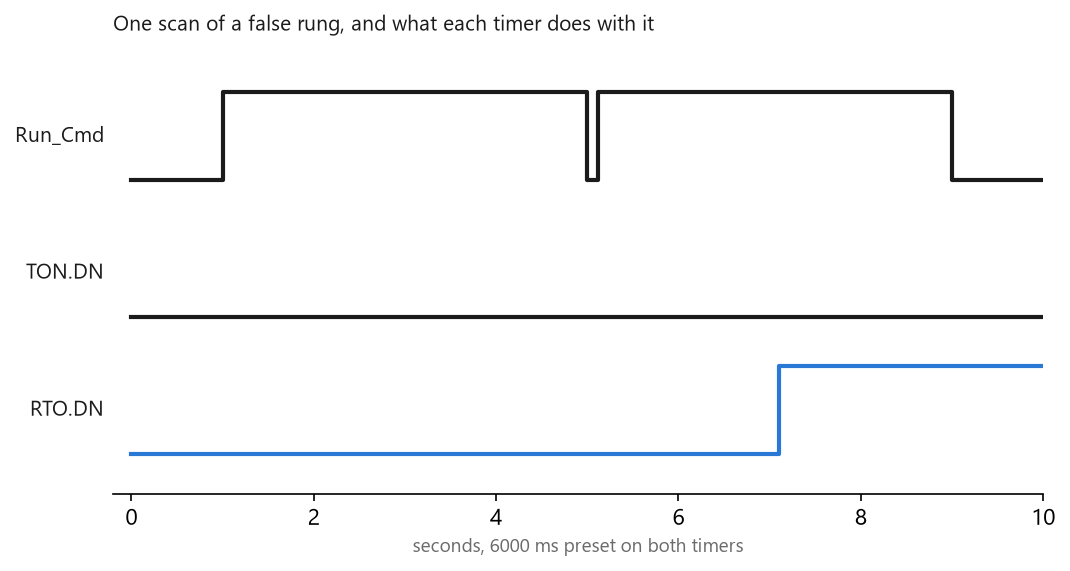
The dip at five seconds is one scan wide. It is enough to send the TON accumulator back to zero, and from there there is never another six clear seconds before the next dip.
Nothing is broken.
Something upstream is dropping the rung for a scan and putting it straight back. A one-shot in the wrong place, a start command re-evaluated from a comparison whose operand moves, an input the controller read twice in the same scan and got two different answers from because the I/O update is asynchronous to logic execution. The rung looks true every single time you go online and look at it, because it is true 99.9% of the time, and the 0.1% is shorter than the tag monitor’s refresh.
The TON does exactly what its execution table says. Rung false, .ACC to zero.
It starts again from nothing, it will never finish while the dip keeps happening, and nothing about any of that is a fault — no bit sets, no message appears, and the controller is behaving exactly as documented while the machine does not start. The dead end is the task period, and it is convincing because it is nearly the right shape. A timer behaving oddly feels like a timing problem, so somebody moves the routine into a faster periodic task, and then lengthens the watchdog, and the timer carries on not finishing. Neither setting has the slightest bearing on whether the rung was momentarily false. A timer inside a routine that is not being scanned at all is a genuinely different failure with a different signature, and it is covered along with the other scan-order traps in common PLC programming mistakes.
Two ways to find the real cause. Put Timer.ACC on a trend rather than a watch window, because a watch window updates far too slowly to show a reset that lasts one scan, while a trend draws it as an unmistakable sawtooth. Or latch the evidence: drop an RTO on the same rung condition alongside the TON, and if the RTO climbs while the TON does not, the condition is not continuously true and you can stop reading the timer logic.
That second trick is also why the RTO in the chart above reaches its preset at 7.1 seconds while the TON never does. Same rung, same preset, different contract.
Siemens answers this differently, and the difference is a checkbox
Take the same question to an S7-1200 and it stops being a question about instructions.
It becomes a question about where the instance data lives.
The S7-1200 system manual, V4.6, is specific. If a run mode session ends with stop mode or a CPU power cycle and a new session starts, the timer data from the previous session is lost, unless the timer data structure is specified as retentive, and that applies to TP, TON, TOF and TONR alike. Then it adds the detail that actually decides the job: when you accept the defaults in the call options dialog after placing a timer instruction, you are automatically assigned an instance DB which cannot be made retentive, and to make your timer data retentive you must use a global DB or a multi-instance DB instead. Read that twice, because it means the Siemens answer to “will this timer survive a power cycle” was decided at the moment somebody clicked OK on a dialog, possibly years before you arrived, and the fix is not a different timer instruction. It is moving where the instance data lives. TONR is the retentive on-delay on that platform and it resets through its R input, but a TONR sitting in an auto-created single-instance DB still comes back from a power cycle at zero, and it will do that quietly, in a block that looks correct.
Do not carry either platform’s habits to the other. Retentive on Logix is an instruction property and stops at the power supply. Retentive on S7 is a memory property, survives a power cycle by design, and is switched on per tag rather than per instruction. The Siemens timer example walks the instruction side of that.
What to check next
Put the accumulator on a trend before you put it on a watch window. One scan of a false rung is invisible in the tag monitor and unmistakable as a sawtooth in a trend, and that one change of tool settles most of these inside a minute. Then go looking for the RES: search the project for the timer’s tag name and count the hits, because an RTO with exactly one hit is a bug that has not happened yet. If the accumulator turns out to be fine and the argument is really about the preset, the arithmetic for picking a number that will not nuisance-trip is worked through in setting a conveyor jam timer from zone length and belt speed, the plain instruction reference sits in timer and counter instructions, and the start-stop rung these usually hang off is in motor start/stop via timer.