
A TON with a .PRE of 5000 that sits in a subroutine only called in Auto, with its rung left true, is already done on the first scan back after twenty minutes in Manual. Publication 1756-RM018A-EN-P prints the arithmetic that explains it, ACC = ACC + (current_time - last_time_scanned), so the timer bills the whole gap to one scan and the five second delay you drew never happens.
Six mistakes are below. They are the common PLC programming mistakes that cost time, rather than the ones that make tidy lists, and each gets the symptom you see at the panel, the line in the vendor document that accounts for it, and what to do instead.
The examples are Logix, because that is where the behaviour is documented in print. Four of the six describe any controller that scans.
| What you are looking at | Where to start reading |
|---|---|
| A stop that worked for a year and then did not, with no fault anywhere | The stop input is wired normally open and the broken wire looks like a healthy button |
| An output bit sitting at 1 while the field device stays dead, and a force makes it work | Two OTEs on one bit, and the later rung wins every scan |
| A delay that sometimes delays and sometimes fires the instant a mode changes | The timer rung is not being scanned continuously, so .ACC arrives in lumps |
| A reject that fires on a good part, roughly once a shift, never while you watch | One input read twice in a scan, with an RPI update landing between the two reads |
| A totaliser that reads low, with no fault and nothing in the log | The periodic task is overlapping and the controller is discarding triggers |
| A latched alarm or a sequence step that survives a fault, a clear and a return to Run | Prescan resets state-based instructions and leaves retentive bits alone |
The stop button that only stops while the wire is good
Symptom: the machine stops on the button during commissioning, passes every test, and eighteen months later a conductor chafes through in a drag chain and the conveyor keeps running.
The HMI shows the stop input as not pressed. Which is exactly what it shows when nothing is wrong.
The cause is a stop drawn the same way a start is drawn.
A normally open field contact, examined with an XIC, energising a stop bit when it closes. Break that wire and the controller can no longer tell a healthy button from no button at all. Publication SGI-1.1, August 2009, is blunt about it: circuits critical to personnel safety should initiate the stop function “through deenergization rather than energization of the control device”, and the comment underneath gives the reason in plain words, so that broken wires or corroded contacts do not go undetected. That sentence was written about relay logic and it has not aged. The predominant failure mode the standard is worried about is a solid state device failing in the ON condition, which is the one case where the program cannot help, because the program sits downstream of the failure.
So wire stop buttons, end of travel limits and pull cords normally closed, carrying 24V while the machine is permitted to run, and examine them with an XIC. Losing the wire then drops the permissive on its own. The same publication is equally clear that an emergency stop belongs to an electromechanical device independent of the solid state logic, which is why that chain goes through a safety relay or a safety controller while the standard controller gets a copy for annunciation only. If you are building one, dual-channel E-stop on GuardLogix has the wiring and the reset logic.
The dead end is the button itself.
Everybody pulls the contact block first and finds it perfect on the bench. The failure is nearly always the wire, the terminal or the connector where the cable enters the moving section.
Test it the other way round. With the machine running in a state you are happy to lose, lift the field wire.
If it keeps running, the polarity is wrong and no program will fix it.
Two OTEs, one bit, and whichever rung runs last
Symptom: the tag monitor shows the output bit at 1, the field device stays dead, and a force makes it work.
An OTE writes its bit every time it executes, with no memory and no arbitration between instructions.
Rung true, bit set. Rung false, bit cleared.
Forcing the bit proves the module and the field wiring are fine. It proves nothing at all about the logic.
Put the same bit under two OTEs in two routines and the one that executes later overwrites the earlier one, every scan, forever. The module takes the tag’s value when it sends at its RPI, and for almost all of every scan that value is whatever the later OTE wrote. Rockwell’s note on the instruction in 1756-RM018A-EN-P says unexpected operation may occur if output tag operands are overwritten, which is a mild way to describe an output that can never come on.
The cross reference lists destructive writes separately from plain references. Sort on that column.
One owner per bit, then.
If two pieces of logic must command one output, give each a request bit and OR them in the rung that owns the OTE.
OTL is the deliberate exception and behaves differently on purpose. It sets the bit, and a false rung leaves it alone. Remember that for the prescan section further down.
A timer only moves when its rung is scanned
This is the one that costs whole days, because the logic reads correctly and the fault is in when the logic runs rather than in what it says.
1756-RM018A-EN-P describes how a Logix timer runs, and it is worth reading before you trust one.
The instruction subtracts the time of its last scan from the current time, adds the difference to .ACC, then stores the current time ready for next time. The timer is reading a clock rather than counting scans, and it only reads that clock at the instants the instruction is executed. Skip that instruction for twenty minutes with its rung still true and nothing happens to .ACC for twenty minutes. Execute it once more and the entire twenty minutes arrives in a single update, the preset is passed on the way through, and .DN comes on before the operator’s hand is off the selector switch.
| Where the timer sits | What .ACC does |
|---|---|
| A rung in a continuous task, scanned every pass | Advances smoothly. Resolution is the scan time. |
| A rung in a 500 ms periodic task | Advances in 500 ms steps. A 200 ms preset cannot expire sooner than one task period after the rung goes true. |
| Inside a JMP zone that is being jumped over | Frozen while skipped, then jumps by the whole skipped interval on the first pass back. |
| In a subroutine called only in certain modes | The same jump, and the timer tag may be shared with another caller. |
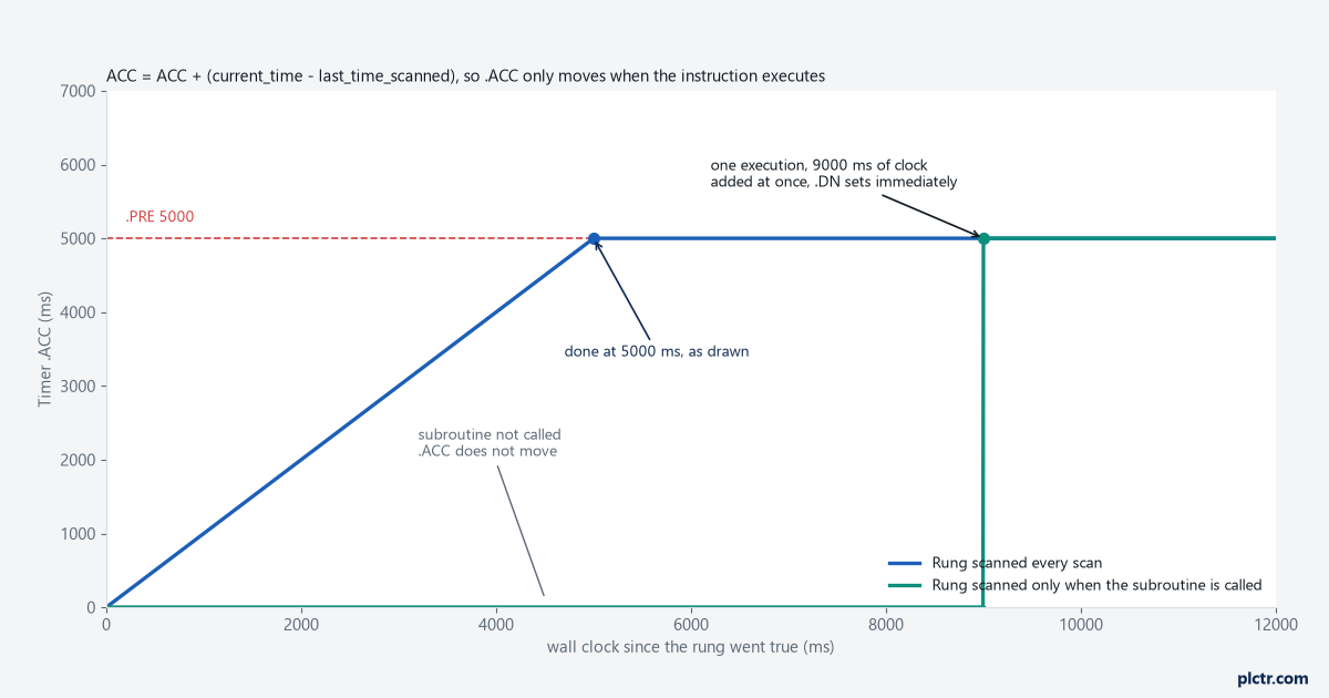
Jumped logic is not scanned. The manual says so under JMP and LBL, and adds that critical logic belongs outside the jumped zone.
1756-RM094N-EN-P is more specific about subroutines. If a subroutine needs a timer, pass the complete timer tag in as an input, return it as an output, and store it in a buffer tag outside the subroutine.
That guideline exists because two callers sharing one TIMER structure is a bug which only shows up when both paths get exercised. On a lot of machines that means the week after commissioning.
The time base is always 1 ms, so a two second timer takes a .PRE of 2000.
On CompactLogix 5380, ControlLogix 5580 and ControlLogix 5590 controllers the TIMER_T structure uses the TIME data type, with microsecond fidelity.
A negative .PRE or .ACC is a major fault, type 4 code 34. The rest of that table is in Allen-Bradley faults, read the type and code.
The dead end on this one is the task watchdog.
A timer behaving strangely feels like a timing problem, so the watchdog gets raised and the period gets changed and the timer carries on jumping. Neither setting decides whether the rung is scanned.
One input, two reads, two answers
Symptom: rung 12 sees the photoeye blocked, rung 40 in the same scan sees it clear, and the reject arm fires on a good part.
Once a shift, never while you are watching, and it survives every inspection because the logic is correct.
1756-RM094N-EN-P states the mechanism on page 95, in a sentence worth memorising.
I/O values update at the requested packet interval, that update is asynchronous to the execution of logic, and so an I/O value in the controller can change in the middle of a scan.
Nothing in a ladder routine is protected from that.
If a decision depends on one input holding the same value in two places, the program has to make it so. The cheap fix is a buffer: copy the input word to a buffer tag in the first routine of the program and reference the buffer everywhere else. Program input parameters do the same job with no code at all, because their values are refreshed before each scan of the program and do not change during execution. The manual says exactly that, and adds that with input parameters you do not need to write code to buffer inputs. On a program that already uses parameters this costs nothing, which makes it a habit worth forming before the day it matters.
Produced and consumed tags carry the same exposure, and the manual gives them the same answer.
CPS, the synchronous copy, is for structures rather than bits. Use it only when what you are buffering is larger than 32 bits, because while CPS runs no I/O update and no other task can touch the data, and tasks that try to interrupt it are delayed until it finishes. That is the property you want for a produced or consumed structure, and the same property that ruins a fast task if you sprinkle CPS everywhere.
The same manual gives the rule for the RPI: set it to 50% of the rate at which you need new data. Need it every 80 ms, configure 40 ms.
Change of state data on EtherNet/IP is held at the adapter until a quarter of the RPI has passed. Numbers in EtherNet/IP setup, RPI and faults.
Your 20 ms task is not running every 20 ms
Symptom: a totaliser that adds a fixed increment per execution reads low against the flow meter, and a filter tuned in the simulator behaves differently on the machine.
No fault, no message, nothing anybody looks at.
The cause is task overlap. If a periodic or event task is triggered while still running from the previous trigger, 1756-PM005M-EN-P says the controller disregards that trigger.
Nothing is queued. The task does not restart. The trigger is dropped.
Detection takes a minute. Right click the task, open Properties, select the Monitor tab and read Task Overlap Count. For logic that has to know, a GSV on the FaultLog object returns MinorFaultBits, where bit 6 indicates an overlap occurred for a task. Overlaps log a minor fault rather than a major one, which is why nothing stops and why nobody hears about it.
The watchdog is a separate mechanism, and confusing the two costs an afternoon.
It defaults to 500 ms, can be set from 1 ms to 2,000,000 ms, and runs from the moment the task is initiated until every program in the task has finished, interruptions by other tasks included. Exceed it and you get a major fault instead of a silently dropped execution. If the same watchdog fault occurs twice during one logic scan the controller enters Faulted mode whether or not the fault handler cleared it, which is the part people discover on the third attempt to nurse a machine through a shift.
With no continuous task in the project, the system overhead time slice has no effect at all. Measuring the rest is in PLC scan time and cycle time.
What prescan clears, and what it quietly leaves
Symptom: major fault, Clear Majors, back to Run, and the latched alarm is still standing while the sequence picks up at the step it was on.
Half the plant believes the controller remembers, the other half believes it should have cleared everything.
Both are half right.
1756-RM094N-EN-P says that on transition to Run the controller prescans logic to initialise instructions and resets all state-based instructions, naming OTE and TON, and that during prescan input values are not current and outputs are not written.
What prescan does not do is touch a retentive bit.
The execution table for OTL lists its prescan action as not applicable, so a latched bit walks through prescan with its value intact. That is designed behaviour, and it is why latching a step number is a decision rather than a convenience.
Structured text has its own version, and it is a real trap because the two operators look almost identical:
(* Logix Structured Text *)
Alarm_Latched := Alarm_Latched OR Level_HH;   (* left in its last state through prescan *)
Pump_Cmd [:=] 0;                              (* forced to 0 during prescan *)
The bracketed assignment resets the value during prescan. The plain one leaves the tag in its last state.
One pair of square brackets is the entire difference between those two lines.
Pick the wrong one for an output command and the pump is commanded on the moment the controller goes to Run, before a single rung of interlocking has executed.
First scan is a different event again. The controller sets S:FS for one scan after prescan, and also on the first scan of a program that has just been uninhibited, so an initialisation routine can run more than once in the life of a download. If yours zeroes a production count, that is worth knowing before somebody uninhibits a program at 3am. The detail is in the PLC first scan bit.
Frequently asked
Is writing the same bit from two places ever acceptable?
With OTL and OTU, yes, because neither is destructive on a false rung. With OTE, keep it to one.
Does buffering inputs cost scan time?
A copy of a 32-bit input word is not measurable. CPS is the one to ration, because it blocks I/O updates and every other task while it runs.
Does a timer in a periodic task keep accurate total time?
Yes, .ACC comes from the wall clock. What you lose is resolution: a 100 ms preset in a 250 ms task means nothing.
How do I tell a task overlap from a task that is simply slow?
Overlap increments Task Overlap Count and logs a minor fault. A task that runs too long trips its watchdog and produces a major fault.
Next step
Two checks, an hour each.
Open the cross reference for the ten output bits that matter most on your machine.
Count the destructive writes on each. That list is shorter than people expect and the exceptions are always the interesting part.
Then lift the field wire on one stop input with the machine in a state you can afford to lose. If it keeps running, you have found the mistake that outranks the other five.
After that, ControlLogix ladder troubleshooting, rung by rung is the method for the rest.
Primary sources: Rockwell Automation, Logix 5000 Controllers Instruction Set Reference Manual, publication 1756-RM018A-EN-P, September 2025; Rockwell Automation, Logix 5000 Controllers Design Considerations, publication 1756-RM094N-EN-P, September 2025; Rockwell Automation, Logix 5000 Controllers Tasks, Programs, and Routines, publication 1756-PM005M-EN-P, September 2025; Rockwell Automation, Safety Guidelines for the Application, Installation and Maintenance of Solid State Control, publication SGI-1.1, August 2009.