Safety Feedback on a Kinetix 5700: What SFX and the Safe Speed Functions Need From the Encoder
A VPL-B0631T-W gives 512 cycles per motor revolution and a VPC-Bxxxx-Q gives 4096. Put the wrong one of those two numbers into the Motion Safety instance and the drive catches you: the DSL diagnostics compare the configured resolution against the device that is actually plugged in and post Invalid Configuration. Put the right resolution in and the wrong conversion constant into the Scaling category, and nothing faults at all — the safely-limited speed you commissioned is simply not the speed anybody thinks it is.
That asymmetry is the thing to carry through this whole subject. The drive checks what it can see. It cannot see your gearbox.
Everything below is the 2198-xxxx-ERS4 safe motion-monitoring inverter, with the numbers from the Kinetix 5700 safe monitor functions safety reference manual.
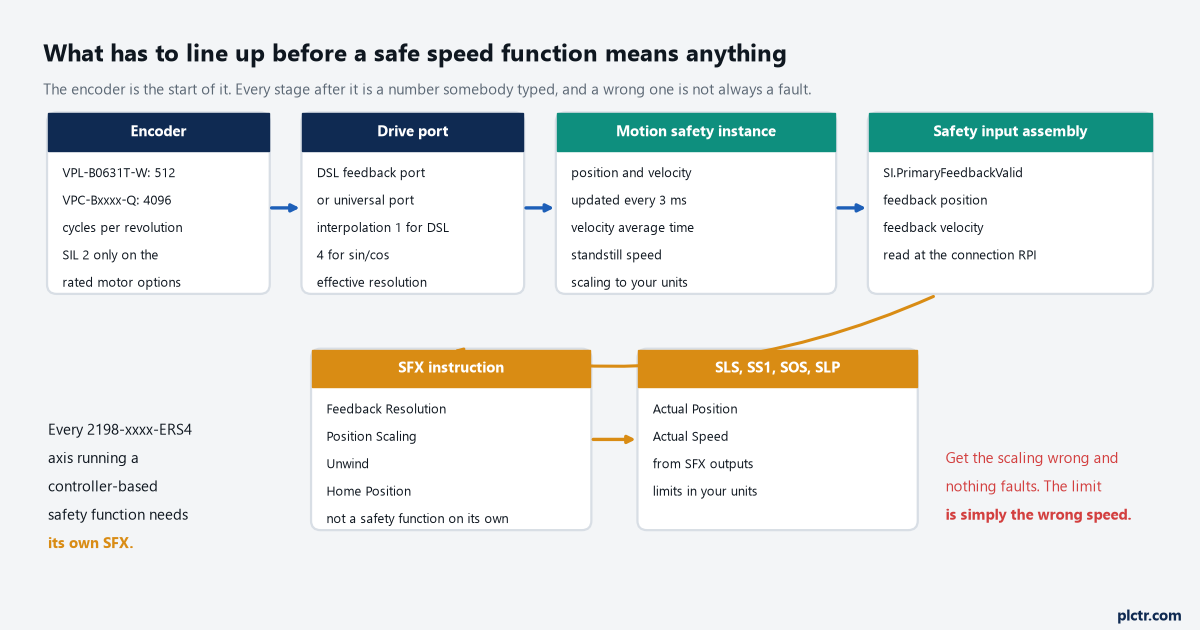
Four stages between the shaft and a limit. Two of them the drive can verify, and two of them are arithmetic nobody checks but you.
Which encoder gets you a rating
Any motor in the pull-down will configure. Only some of them come with a number you can use.
The manual lists Kinetix VPL, VPF, VPH and VPC motors, Kinetix MMA motors with the -S2 or -M2 encoder option, and VPAR electric cylinders with -Q or -W as SIL 2 rated; anything else can be selected and will run, but the SIL Capability field on the Primary Feedback page reads Unknown, and that is the end of the conversation with whoever is signing the safety file. The device is the port rather than the part: DSL Feedback Port or Universal Feedback Port, with the feedback type list changing depending on which one you pick. Two numbers on that page do the work. Cycle Resolution is the raw count from the device, 4096 cycles per revolution for a -Q, 512 for a -W and for the VPL-B063 and VPL-B075 frames; Cycle Interpolation is 1 for DSL and 4 for sin/cos; and Effective Resolution, which is the product of the two, is what every later calculation is built on.
A -Q encoder and a -W encoder differ by a factor of eight. A conversion constant copied between two machines will not tell you that.
What the second encoder actually buys
Dual feedback raises the rating of the speed functions. It does not raise the rating of the position functions, and that catches people building a safely-limited position zone.
For SIL 3 and PL e the primary has to be one of the SIL 2 rated motor encoders on the motor feedback connector, with a sin/cos device on the universal feedback port as secondary; the secondary does not itself need a SIL rating, though you have to justify its suitability, and the drive’s diagnostics for a sin/cos device are the 5 V and 9 V supply monitors and the SIN² plus COS² vector length test. The footnote under that table is the important sentence in the whole chapter: dual-channel SIL 3 and PL e apply only to velocity discrepancy checking and to functions that check speed. SLP and SDI check position, SS2 and SOS can be configured to check position, and the drive does not perform position discrepancy checking at all, which caps position-based safety functions at SIL 2 and PL d. Getting SIL 3 on a position function means writing dual-channel position comparison in the GuardLogix yourself, as safety logic you then have to validate.
Two encoders and a Category 4 architecture still gives you PL d on an SLP zone.
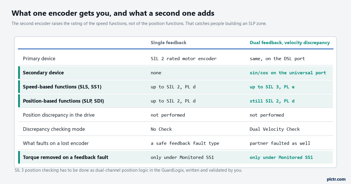
The row that decides projects is the position one. It stays at SIL 2 whatever you spend on encoders.
Velocity average time, and the delay you are buying
The safety instance computes velocity by differencing position samples taken every 3 ms, and then averages them.
Velocity Average Time sets how many of those samples go into the moving average: the count is the time divided by 3 ms with the remainder truncated, so anything you type between 0 and 5 ms gives a 3 ms window, 6 to 8 ms gives 6 ms, and so on up. Why it matters is resolution. With a low-resolution encoder at low speed the shaft does not move enough between samples, so the reported velocity jumps between zero and a large number, and averaging is what turns that into something a limit can be compared against. The manual’s own table puts the trade in plain numbers: at an interpolated count of 512, a 100 ms average resolves 1.171875 rpm and a 1000 ms average resolves 0.117188 rpm. There is a floor underneath the setting too — set the average time shorter than the safety connection RPI and the velocity aliases, because changes between assembly updates never reach the controller at all, and the reported speed can differ from the real one.
Longer window, finer resolution, later answer. The later answer lands in the stopping distance.
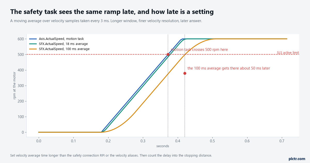
The same ramp, the same limit, three different moments at which the safety task decides the limit has been crossed.
The safety connection’s own minimum RPI on this drive is 6 ms, which is the same connection that carries safe torque off — the two share the budget, and hardwired or networked safe torque off covers what else is in it.
Scaling to a unit the guard actually cares about
Counts per revolution is not a unit anybody guards a machine in.
The Scaling category is where the motor’s counts become the thing the risk assessment talks about: Position Units is free text you invent, Time is seconds or minutes, and the conversion constant is the number of counts in one of your units. The manual works it through on a rotary knife twice. One blade coupled straight to a VPC-Bxxxx-Q is 4096 counts per knife revolution and the arithmetic is nothing. Two blades behind a 10:1 reduction is 4096 counts per motor revolution, times ten motor revolutions per load revolution, divided by two knife cuts per load revolution — 20480 counts per knife cut. Nothing in the drive knows whether your gearbox is 10:1 or 12:1, and nothing will fault if you use the wrong one; the SLS limit you then set in knife cuts per second is quietly out by the ratio of the error.
Write the conversion constant out longhand in the design file, with the gearbox ratio in it. A number on its own cannot be checked later.
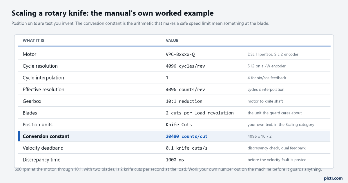
Every row above the conversion constant is a fact about hardware. The conversion constant is the one line where an assumption becomes a safety limit.
Where two feedback devices are compared, the Discrepancy Checking page takes Mode set to Dual Velocity Check, a Time in milliseconds, a Ratio for the gearing between primary and secondary, and a Velocity Deadband in your own units — 0.1 knife cuts per second over 1000 ms in the manual’s example. The warning attached to it is worth reading before you pick a deadband: a high gear ratio between the two devices means a large primary movement is a very small secondary increment, and that alone can produce unexpected dual-feedback faults.
What SFX does, and what it is not
SFX is required and SFX is not a safety function. Both of those are true at once.
The Safety Feedback Interface instruction takes feedback position in counts and feedback velocity in feedback units per second out of the safety input assembly, and puts out Actual Position in your position units and Actual Speed in your units per second or minute. It also holds the unwind for a rotary application and sets a reference position from a home input. Every controller-based safety function on an ERS4 axis needs one — SS1 takes its Actual Speed from it, SLS compares against it — and the manual says plainly that although SFX is a safety instruction, on its own it performs no safety function. Its inputs come from two places you have already filled in: Feedback Resolution is the Effective Resolution from the Primary Feedback page, and Position Scaling is the conversion constant from the Scaling page. Homing the instruction is only needed if a position-based instruction such as SLP is in use, and it is not the same thing as homing the axis — the manual is explicit that this has nothing to do with the MRP instruction.
One SFX per axis. Not one per zone, and not one per machine.
When feedback faults, and when that removes torque
A safety feedback fault does not stop the machine by itself. That surprises people the first time.
The motion safety instance runs periodic diagnostics on the feedback device, and where it finds a problem the Safe Feedback object — class code 0x58, attribute 0x09 — carries the reason, readable with an explicit message. The named types are worth knowing because they point at different things: Invalid Configuration is the configured resolution not matching the device; Sin² + Cos² Error and Feedback Signal Lost point at the analogue wiring of a sin/cos device; Feedback Data Loss points at an open circuit on a DSL connection; Supply Voltage Error points at the feedback supply or at the drive itself; Discrepancy Error and Partner Faulted only exist in a dual feedback configuration. What the manual then says about consequences is the part to design around: a safety feedback fault only causes torque disable under two conditions together, SS1 configured for Monitored SS1 mode and an SS1 request received from the safety controller. Outside those conditions the machine keeps running with a degraded safety function, and the only thing telling you is a status bit.
On a dual-axis inverter some of those faults are duplicated to the other axis, so a fault on axis 1 is a reason to check the wiring on both.
One honest gap. The fault-type numbering in the troubleshooting table and the number quoted in the manual’s own validation checklist do not agree — the checklist asks you to verify a Fault Type 100 described as Feedback Invalid, while the fault table gives 100 a different name. I would not publish a code table off the back of that; read the type back with the explicit message on your own drive and record what it returns before writing it into a maintenance procedure.
Next step: run the manual’s own validation trend before anyone relies on a limit. Put Axis_Name.ActualPosition, Axis_Name.ActualSpeed, SFX_Name.ActualPosition and SFX_Name.ActualSpeed on one chart, run the machine through its normal range, and confirm the standard and safety values track each other the way your scaling says they should. Then disconnect the feedback and confirm the fault appears and SI.PrimaryFeedbackValid drops. For the motion side of the same axis, the Kinetix 5700 motion control article covers what the axis is doing while all this is watching it, and wiring an encoder to a high speed counter input covers the non-safety case where the counts come into a controller instead.