The takeaway conveyor’s 25B-D010N104, a 480 V PowerFlex 525 on a 4 kW motor, ran all day and tripped F005 OverVoltage on the first stop of every shift, with the PowerFlex 525 decel time at 2.00 s, b005 [DC Bus Voltage] sitting at 812 V in the fault history, and a belt carrying forty cartons when it happened. Empty, it stopped fine. Loaded, the belt and the cartons and the gearbox all carried kinetic energy the motor had to get rid of in the 2.00 s that P042 [Decel Time 1] gave it, and a motor being dragged down by its drive faster than the load wants to slow is a generator whose only sink is the drive’s DC bus capacitors. The manual’s line for F005 says it plainly: bus overvoltage can also be caused by motor regeneration, extend the decel time or install the dynamic brake option. On this drive there was a third cause, and it was the one that mattered: A550 [Bus Reg Enable] had been set to 0, Disabled, by somebody who wanted exact stopping distances, and the regulator that would have stretched the ramp on its own was switched off. Everything below is that drive, the four parameters that decide what happens to the bus on a stop, and b005 trended through the stop before and after each change.
The bus regulator, the decel time, the stop mode, the brake resistor. In that order, because the first one is free.
What a loaded belt does to the DC bus
The drive rectifies 480 V into a DC bus that idles at about 650 V, and the manual’s trip point for a 380 to 480 V input drive is 810 V DC – equivalent, the same table says, to a 575 V AC incoming line.
That 160 V of headroom is what the regeneration has to fit inside. When the drive commands a frequency below the motor’s actual speed, the motor generates back into the inverter, current flows the wrong way through the IGBT diodes, and the bus capacitors charge; nothing else in a standard 525 can absorb it. How fast the bus climbs depends on how much energy the load has and how quickly the ramp asks for it, which is why the empty belt was fine and the loaded one was not: same ramp, several times the inertia. The drive’s ramp is defined against P044 [Maximum Freq], so P042 is not the time this stop takes – decel rate is Maximum Freq divided by Decel Time, 60 Hz over 2.00 s is 30 Hz per second, and a stop from 50 Hz takes 1.67 s. On a 0.500 m/s belt that is a stopping distance of 0.42 m, and that number is the reason somebody had shortened the ramp and switched the regulator off: the accumulation zone downstream needed cartons to stop inside the zone. b005 reads the bus, filtered, 0 to 1200 V, and the value the fault history stores is the value at the trip, which on this drive was 812 V.
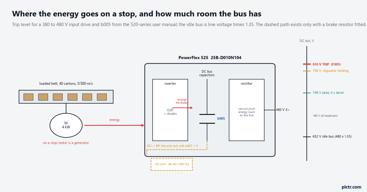
On a stop the motor is a generator and the bus capacitors are the only load. 160 V of headroom, a filtered reading in b005, and the trip recorded at 812.
The stopping distance was the design input. The decel time was chosen to hit it, and the fault was the cost.
The PowerFlex 525 decel time, and the three parameters around it
Four parameters decide the outcome, and the manual documents how they interact in a way the parameter list on the HIM does not show.
A550 [Bus Reg Enable] defaults to 1, Enabled, and its job is in the preface’s attention note: the bus regulator is extremely useful for preventing nuisance overvoltage faults from aggressive decelerations, overhauling loads and eccentric loads – and it does that by making the actual deceleration longer than the commanded one when the bus rises, holding the bus under the trip. The same note lists the cost: fast positive changes in line voltage can cause uncommanded positive speed changes, actual decel times can be longer than commanded, and if the drive stays in that state for one minute it produces a stall fault, F006. So a regulated stop is a stop whose length the drive decides. P042 [Decel Time 1], 0.00 to 600.00 s and 10.00 s by default, is the commanded ramp, referenced to P044; A443 [Decel Time 2] is a second ramp the digital inputs select through the Acc/Dec Sel options, which is how a drive can stop gently in normal operation and hard when the zone logic asks. P045 [Stop Mode] decides whether there is a ramp at all: 0, Ramp CF, is the default and clears an active fault on the stop command; 5, Coast, drops the output and lets the belt roll, with no regeneration and no stopping distance either; 10 and 11, PointStop, calculate a ramp to stop in a fixed distance regardless of speed, and the manual recommends braking resistors or A550 at 0 for it – which is where the 0 on this drive came from, copied from a positioning conveyor elsewhere in the plant. A437 [DB Resistor Sel] enables an external dynamic brake resistor across DC+ and BR, with A438 [DB Threshold] setting the bus level, 10 to 110%, at which the brake IGBT starts to modulate; and the IMPORTANT under A437 is the interaction that decides the design: when A437 is greater than 0, A550 does not take effect. The resistor replaces the regulator; you do not get both.
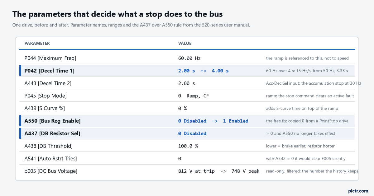
Two rows changed: A550 back to Enabled and P042 to 4.00 s. A437 stayed at 0 because the stopping distance could live with the longer ramp; the day it cannot is the day A437 goes to 1 and A550 stops mattering.
A437 above zero switches A550 off. That single line is the whole choice between a longer stop and a hotter resistor.
What b005 did through the stop, three ways
The trend is b005 read every 20 ms over EtherNet/IP through a datalink, the way the command word article sets one up, with the stop command marked and the 810 V trip drawn on it.
With A550 at 0 and P042 at 2.00 s, loaded, the bus climbed from 652 V to 812 V in 0.9 s of the ramp and the drive tripped F005 with the belt still moving at 22 Hz – which is worse than a controlled stop from every point of view, because a faulted drive coasts. With A550 back at 1 and nothing else changed, the same stop reached 796 V, the regulator held it there by letting the ramp slip, and the belt stopped in 2.9 s instead of 1.67, with 0.73 m of travel and no fault; that is the free fix, and on a belt with no stopping distance requirement it is the whole fix. With P042 at 4.00 s as well, the bus peaked at 748 V and the ramp ran at its commanded rate, 3.33 s from 50 Hz and 0.83 m of travel, and that is the setting the drive runs on now, with A443 [Decel Time 2] at 2.00 s selected by the zone logic’s digital input for the one stop that has to be short – the accumulation stop with a carton on the eye, which happens at 30 Hz, from where 2.00 s on the 60 Hz reference is 1.0 s and 0.15 m, and the bus barely notices. The number to read off the trend is not the peak. It is the margin to 810 at the worst stop of the day, the loaded one at full speed, and 748 leaves 62 V for a high line and a hot afternoon.
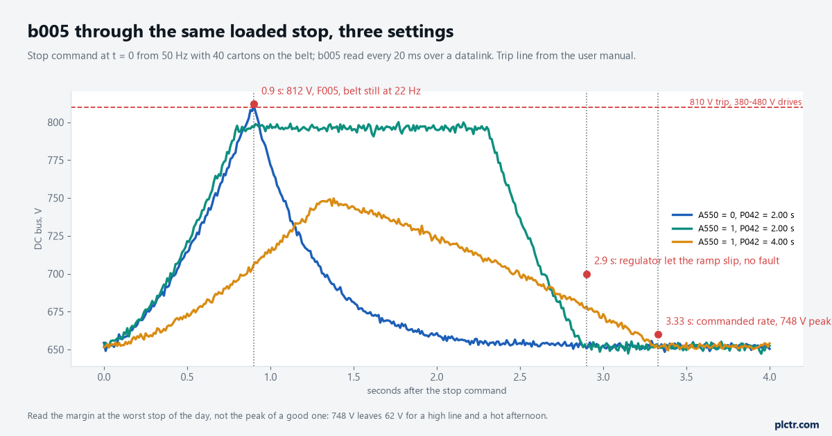
Same belt, same load, same stop command. The regulator alone stops the fault; the longer ramp gives the margin back. The stopping distance is the price of each.
The margin at the loaded stop from full speed is the number. Sixty volts is comfortable; twenty is a fault on the first hot day.
When the distance is not negotiable
A conveyor whose stopping distance is fixed by the layout – the photo-eye’s distance from the zone discharge was set for a stop of 0.42 m and cannot be moved – has run out of parameters and needs somewhere to put the energy.
That is the dynamic brake resistor, and the manual sizes it by drive rating: the 380 to 480 V, 5 hp, 4 kW row gives a minimum resistance of 47 Ω, a resistor of 120 Ω, and the catalogue number AK-R2-120P1K2, with fuse protection listed in the same table. A437 goes to 1, Normal RA Res, which protects the resistor at a 5% duty cycle, or to a value from 3 to 99 to declare the duty cycle the resistor can take, and 2, NoProtection, leaves the resistor’s survival to you; the ATTENTION under A438 is about exactly that, because a threshold below 100% makes the brake more responsive and can have the IGBT modulating continuously into a resistor rated for a few percent. On a conveyor that stops thirty times an hour from full speed with a loaded belt, the duty cycle is the sizing question, not the resistance. With the resistor fitted the bus is clamped by the brake instead of the regulator, P042 goes back to the 2.00 s the layout needs, and the F005 does not come back; what comes back, if the resistor is under-rated, is a resistor thermostat trip, which is a better fault to have because it happens on the bench and not in the fault history.
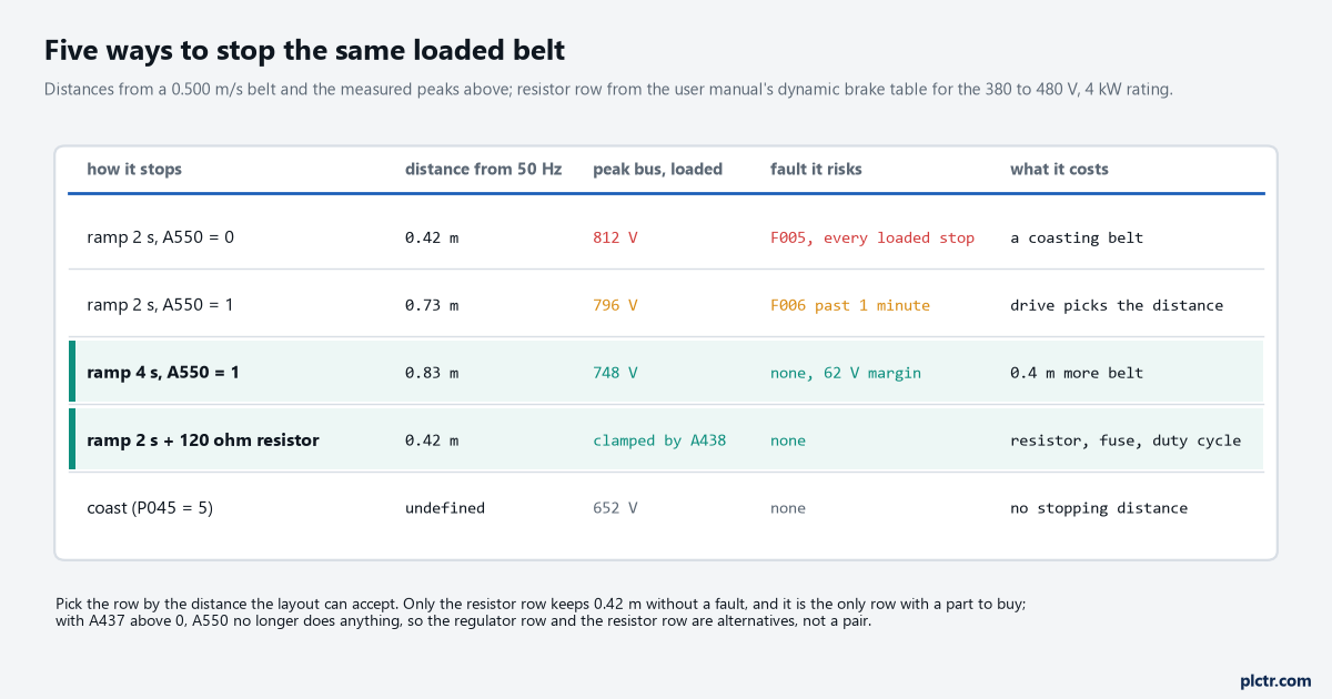
Pick the row by the distance the layout can accept. The resistor row is the only one that keeps 0.42 m without a fault, and it is the only one with a part to buy.
The thing everyone checks first
The incoming line, because the fault text names it first, and it is almost never the line on a fault that only happens on a stop.
F005 on a running drive with no stop in the fault history is a line problem – a transient, a capacitor bank switching next door, the undervoltage article’s opposite – and the fault history with b007 [Fault 1 Code] reading F005 while the drive was at speed says so. F005 whose every occurrence is inside a second of a stop command is regeneration, and the line can be 480 V to the volt. Read the history first, then the parameters in the order above: A550 first, because a 0 there on a conveyor drive was put there for a reason that belongs to some other machine; P045 second, because Ramp CF clears the active fault on the next stop command and hides the count; P042 and A443 third, against the stopping distance the layout actually needs. A541 [Auto Rstrt Tries] with A542 at 0 clears an OverVoltage without restarting the drive, and the manual documents it for exactly that, but a conveyor that clears its own F005 thirty times a shift is a conveyor that coasts thirty times a shift with nobody knowing.
Fault history first, then A550, then the ramp against the distance. The line last.
Next step
Read b007 to b009 and note whether each F005 sits on a stop; then trend b005 through a loaded stop from full speed with the settings as they are and write the peak on the drawing next to the trip point. Put A550 back to 1 unless there is a written reason for 0, and re-run the stop. If the stopping distance the regulator produces fits the zone’s photo-eye placement, lengthen P042 until the loaded peak has sixty volts of margin and put the short stop on A443; if it does not fit, size the resistor from the table for this drive’s row and set A437, and leave A550 where it is, because it no longer does anything. On the accel side the same belt asks the same question the other way round – a loaded start against A484 [Current Limit 1] stretches the ramp and F006 follows after a minute – and the motor control article covers the current side of that.
The fault is the energy with nowhere to go. Give it the regulator, then time, then a resistor, and check the distance after each.