Zone 6’s eye came out of stores as a 42EF-P2KBB-F4, went onto the bracket in place of a 42EF-P2JBB-F4, and from the next 600 mm carton on, zone 6 reported occupied while it was empty and empty while a carton stood on it. One letter in the fifth position of the catalogue number, K for J, is the light operate dark operate choice, and the zone’s logic ran backwards: zone 5 stopped releasing into a zone it believed was full, and the first carton somebody pushed onto zone 6 by hand made it read empty, which is when zone 5 released into it. Nothing was wired wrong. Nothing in the program had changed. The sensor was doing exactly what its part number said, and its part number was not the one on the bracket before it.
Light operate energises the output when the beam arrives. Dark operate energises it when the beam does not.
Everything below is on the twelve-zone line from the photo-eye placement article: a 5069-L320ER CompactLogix, one polarised retroreflective 42EF per zone at the discharge end, each into a point on a 5069-IB16, and zone logic that reads Zone[i].Occupied := Zone[i].PE in a 50 ms task, where PE is true when the beam is broken. The line was commissioned with J models and an inversion in the input map; the swap to a K removed the inversion the program was relying on.
Light operate, dark operate: what the fifth letter does
A retroreflective eye sees its own beam come back from the reflector, so on an empty zone the beam is made and on an occupied zone it is broken. That is the sensing. The output is a separate decision, and 42EF-TD001 makes it in the catalogue number: in the polarised retroreflective row of its product selection table, 42EF-P2JBB-F4 is light operate and 42EF-P2KBB-F4 is dark operate, otherwise the same sensor, and the M models next to them – 42EF-P2MNB-F4 and 42EF-P2MPB-F4 – are “light and dark operate”, which means both outputs on one sensor. A light-operate eye on a zone energises its output when the zone is empty. A dark-operate eye energises it when a carton is there. Put a K where a J was and every empty zone reads as a carton and every carton reads as empty, which is the fault in the first paragraph, and there is no switch on the housing to change it: the choice is in the part number, so it is in the stores list, so it is in whatever the last person typed into the stores list.
K where a J was, and every zone on the line tells the opposite truth.
The orange indicator is the fastest way to find the one that is wrong. 42EF-TD001’s Table 6 lists the orange LED as on when the output is energised and off when it is de-energised, whichever model it is – so on an empty line every retroreflective J on the line shows orange and a K shows nothing, and the one bracket that does not match its neighbours is the swap. The same table gives the two flashing states worth knowing at the bracket: 1.4 Hz is unstable light, the received signal between 0.8 and 1.5 times the switching threshold, which is a dirty lens or a reflector that has been clipped by a corner; 6 Hz is short-circuit protection on the output, which is a wiring fault. The green indicator is power and the margin aid, lit when the sensor is receiving at least 1.5 times the signal it needs.
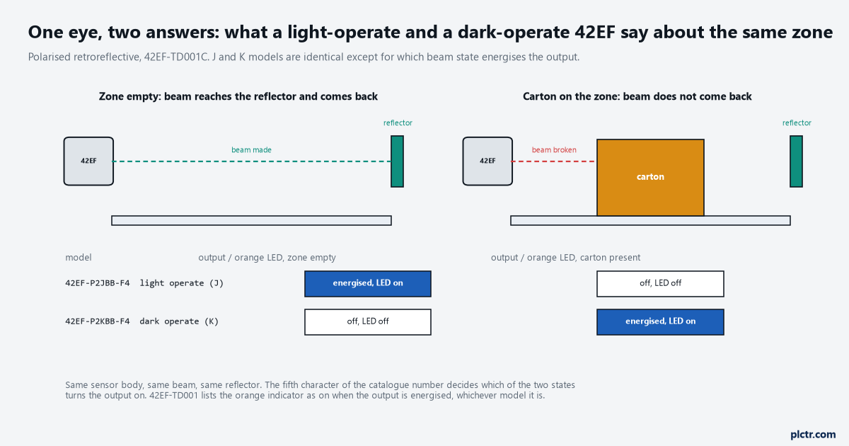
Same body, same beam, same reflector. J energises on beam made, K on beam broken, and the orange LED follows the output on both.
Same eye, same beam, opposite output. The letter is the only difference.
Which one to fit, and it is not the obvious one
Fit the one whose failures look like a carton.
The obvious choice for a zone eye is dark operate, because the input bit then reads true when a carton is there and Occupied := PE needs no inversion. It is the wrong choice, and the reason is every way the sensor can stop working. A cut cable, a sensor that lost its 24 V, a lens fouled to below the switching margin, a reflector knocked off its bracket: each one takes the output to de-energised, and on a dark-operate eye de-energised is “no carton”. The zone reads empty, it reads Ready, and the zone upstream releases a carton into whatever is standing on it. On a light-operate eye with the inversion in the program, the same failures all read as “beam broken”, the zone reads occupied, the zone upstream holds, and the line stops in the right place with a zone that will not accept product until somebody looks at it. That is the choice: a failure that stops the line where the fault is, or a failure that hides a carton. It is one bit of logic per zone and it is the reason the line was commissioned with J models in the first place.
A dead dark-operate eye reads empty. A dead light-operate eye reads carton.
The rule generalises. On a diffuse eye, which sees the carton rather than a reflector, the sense is reversed – light received means a carton – so the failure-safe choice on a diffuse zone eye is dark operate, output energised when nothing is there. Either way the output should be energised when the zone is healthy and empty, so that anything that kills the output looks like a carton.
Energised when empty and healthy. Dead looks like a carton. That is the whole rule.
Normalise at the edge, and only there
The raw input is used in one rung and never again.
The program’s Zone[i].PE means “beam broken” on every zone, and the map that produces it is the one place the sensor’s own sense is allowed to exist: Zone[i].PE := IO_PE[i] XOR Zone[i].PE_Invert, with PE_Invert a per-zone configuration bit, 1 for a light-operate eye and 0 for a dark-operate one. Everything downstream – Occupied, the jam timer, the ownership handshake – reads PE
One reader of the raw input. The cross-reference should show exactly one rung.
(* ConveyorTask, 50 ms - the input map, and nothing else touches IO_PE *)
FOR i := 1 TO 12 DO
    Zone[i].PE := IO_PE[i] XOR Zone[i].PE_Invert;   (* PE = beam broken *)
END_FOR;

(* the induct eye has the M model: two outputs, and they must disagree *)
PEFlt.PRE := 50;
PEFlt.TimerEnable := (IO_PE_Blk[1] = IO_PE_Clr[1]);
TONR(PEFlt);
IF NOT PEFlt.TimerEnable THEN PEFlt.Reset := 1; END_IF;
Zone[1].PE_Fault := PEFlt.DN;
Zone[1].PE := IO_PE_Blk[1] OR Zone[1].PE_Fault;   (* cannot see = treat as blocked *)
The input card sets one condition on the sensor’s output type. 5069-UM004 lists the 5069-IB16 as a 16-point sinking input module, so it wants a sourcing output, and the J and K models list “NPN and PNP” in the output-type column, the standard auto-detecting output that works on either. The M models do not: the complementary-output sensor comes as N for NPN or P for PNP, and only the 42EF-P2MPB-F4 drives a sinking card. Order the N and the two outputs never energise the inputs at all, which the sinking and sourcing article covers from the card side. Four wires on the M model per 42EF-TD001’s wiring diagram: brown positive, blue negative, black to one load and white to the other, and the two loads are two input points.
![Three ladder rungs: the XOR input map from the raw input and the per-zone invert bit into Zone[6].PE, the complementary-output health check timing both inputs equal for 50 ms into PE_Fault on the induct eye, and the induct eye's PE reading blocked when the fault is set](https://plctr.com/wp-content/uploads/photo-eye-light-operate-dark-operate-inverted-zone-logic-2.png)
Rung 80 is the only rung on the line that reads a raw eye input. Rungs 81 and 82 are the second signal on the induct eye, where a carton the eye cannot see costs a collision at the merge.
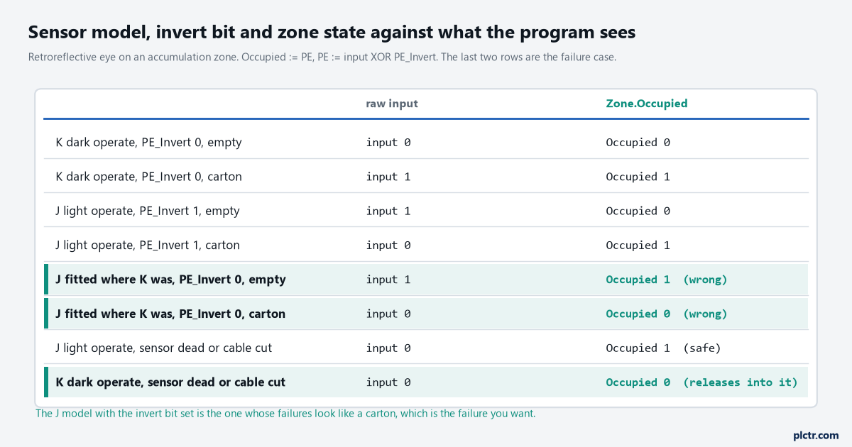
The two rows marked wrong are the swap. The last two rows are the reason the line was commissioned with J models and the invert bit set.
One eye, two signals: where the M model earns its second input
A complementary eye costs one more input per zone and buys the one thing a single output cannot give: proof the sensor is alive.
The M models carry both outputs, light operate on one wire and dark operate on the other, and in a healthy sensor they always disagree – one energised, one not. Both de-energised is a dead sensor, a cut cable, a lost supply or the output’s short-circuit protection holding it off; both energised is a wiring fault. A rung that times the two inputs being equal for 50 ms, one task pass, sets PE_Fault with the zone number, and the zone reads blocked until it clears, because a zone that cannot see must not accept a carton. The price is twelve more inputs on a twelve-zone line, most of a second 5069-IB16, and on the accumulation zones it is not worth it: a dead J model already reads as a carton, which is the safe way to fail, and the zone stopping is the alarm. It is worth it on the induct eye, where a carton the eye did not see is a carton the tracking register never learns about, and on any eye whose only failure mode otherwise is a release into product – a diffuse eye that had to be light operate because of the background, say. Fit it where a blind eye costs a collision, not everywhere.
Twelve more inputs for proof of life. Buy it where blindness costs a collision.
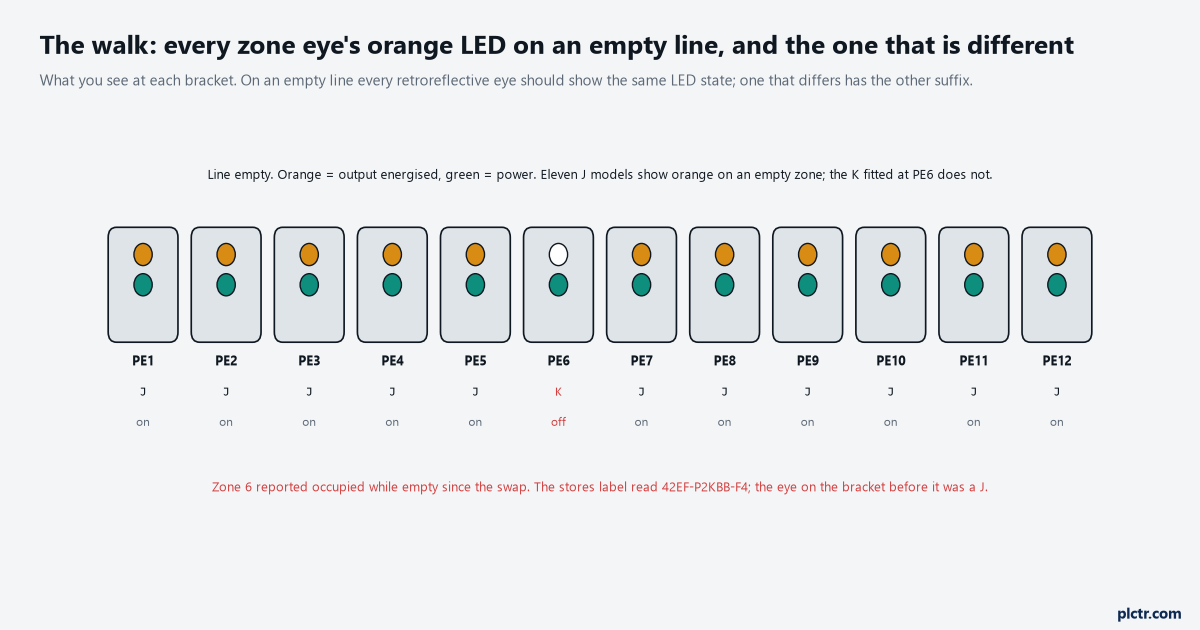
The walk that finds it in five minutes. Every retroreflective eye on an empty line should show the same orange state; the one that differs is the other suffix.
The thing everyone checks first
The wiring.
An inverted zone sends the electrician to the terminals, because inverted looks like a swapped pair, and the pair is checked and the connector is reseated and the card’s LED agrees with the sensor’s LED and nothing is found because nothing is wrong. Then the program gets blamed, and the force goes on to prove it, and the zone works with the input forced, which proves only that the input is inverted. Read the label on the sensor body against the label on the one in the bin it came out of, letter by letter, and then walk the line and read the orange LEDs on an empty line: one bracket that disagrees with eleven is the answer, and it took five minutes. Then look at what else came from the same stores order, because a purchasing system that ordered one K where a J was wanted did not order one.
Eleven orange LEDs and one dark one. Read the part number on the dark one.
Next step
Put PE_Invert on the zone configuration screen next to the setback and the long-product threshold, and put the sensor’s catalogue number on the zone sheet next to it, so the next swap is a one-bit change that somebody can see was made. Then walk the line once with the belts empty and write down the orange state at every bracket, because that list is the check the stores list cannot do. The card side of the same eye – the filter that hides a short beam break, and what a sinking point does with a sourcing output – is in PLC I/O modules: sinking, sourcing, keying and scaling, and where the eye goes on the zone, and how far back, is the setback question.