When a PowerFlex 525 F004 shows up on four drives in the same second, the drives are not the problem and swapping one proves it. F004 is the DC bus falling below the drive’s low voltage limit, and a bus only falls when the supply behind it does. This is how to turn a handheld reading that says everything is fine into a trace that names the culprit, and what to do once it has a name.
The example is a packaging MCC with eight 525s on one 480 V bus, four or five of them faulting together two or three times a week, always the loaded ones.
Why the handheld says the supply is fine
A meter shows you what the bus is doing while you stand in front of it. The event that trips the drives lasts about a second. Steady 478 V on a clamp meter and F004 on four drives are both true statements about the same bus, and only one of them is about the moment that matters.
The second thing the meter cannot see is what the drive is actually protecting. F004 is not a measurement of the incoming line. The drive rectifies the line into its DC bus, runs the inverter from the bus, and trips when the bus falls under the limit for its voltage class. So the fault sits one step downstream of the thing everybody measures, and how far the bus falls depends on the load the drive is carrying at that instant.
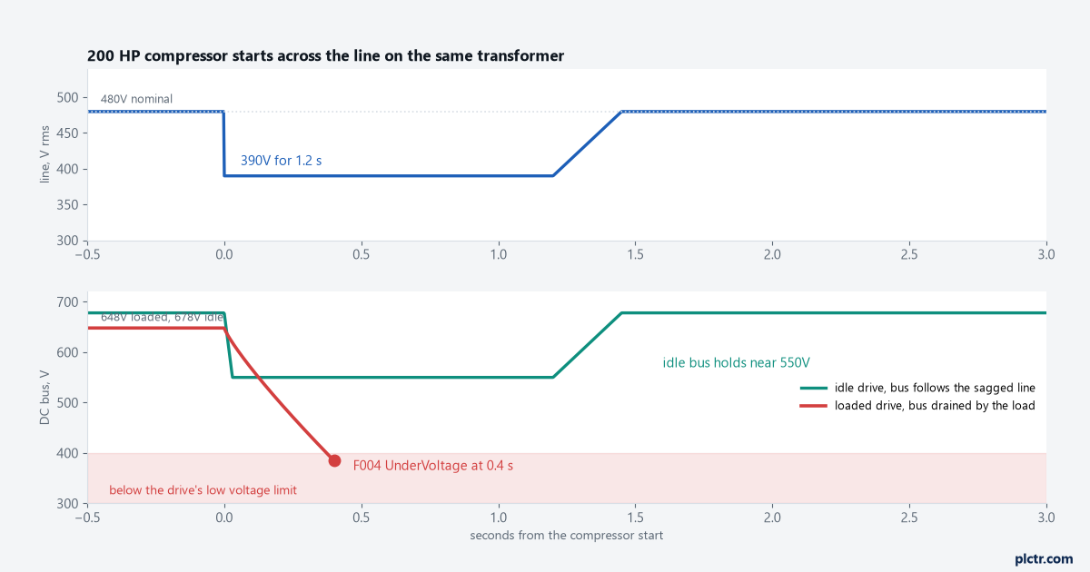
That is the answer to the question everyone asks first: why these drives and not those. An idle drive sits on a bus that nothing is draining. A loaded drive is pulling kilowatts out of the same capacitors. Give both of them the same sag and the loaded one reaches the limit and the idle one never does.
Work out what the bus should be
| Line volts at the drive | Approximate DC bus, loaded | Approximate DC bus, unloaded | Comment |
|---|---|---|---|
| 480 V | 648 V | 678 V | nominal, everything normal |
| 440 V | 594 V | 622 V | inside the drive’s input tolerance |
| 408 V | 551 V | 577 V | the bottom of a minus 15 percent supply |
| 390 V | 527 V | 551 V | measured sag depth on this MCC |
| 360 V | 486 V | 509 V | a loaded drive will not hold through this |
The rectified bus tracks the line peak, so a rough figure of 1.35 times the line under load and about 1.41 times it with no load gets you close enough to reason with. The exact low voltage limit for your drive and voltage class is printed in 520-UM001, and it is worth reading off the page rather than from memory.
Ride through is arithmetic on the bus capacitors. The energy available between the running bus and the limit is half the capacitance times the difference of the squares. Take 470 microfarads as an example figure, a bus starting at 648 V and falling to 400 V, and that is about 61 joules. A drive delivering 2 kW empties it in roughly 30 ms. The same drive idling at a tenth of that load holds ten times longer. Get the real capacitance for your catalogue number out of the drive’s technical data, or from Rockwell if it is not published there, before you quote a figure to anyone. The shape of the answer does not change: ride through is measured in tens of milliseconds, and the sag that trips a row of drives is measured in seconds.
Log the sag instead of arguing about it
A recording meter on the MCC bus for a week ends the discussion, and the log is also what buys the fix.
Landing the leads is the hazardous part, so treat it that way. The clean way is to land them during a planned outage with the bus locked out, tagged and proved dead with a meter rated CAT III 600 V or better. If it has to go on live, that is energised work: a permit, arc rated PPE chosen from the study for that bus, insulated tools, a second person, and clamp on or non contact connections wherever the meter allows them. Nobody lands a test lead on a live 480 V bus alone because a trend chart was wanted by Friday.
Set the recorder for minimum and maximum RMS per cycle, not averages. A one second sag disappears into a ten second average and the report comes back saying the supply is healthy. Record the drive faults alongside it, either from the keypad fault history or from the PLC if the drives are networked, so the timestamps line up.
Then look for what starts when the drives fault. Across the line motor starts are the usual answer: a backup compressor, a chiller, a fire pump test, a large fan. A 200 HP motor at 480 V draws roughly 240 A running and something like six times that when it is thrown straight onto the line. Push 1400 A through an example 500 kVA transformer at around 6 percent impedance and you have lost about 14 percent of the voltage at its terminals, before the feeder and the utility behind it are counted. Use the rating and the impedance off your own nameplate. The point is the size of the step, not this particular transformer. That is how a bus that reads 478 V all day gets to 390 V for a second.
Read the trace and decide what to change
The measured sag on this MCC was 390 V for 1.2 s on every backup compressor start. The idle drives rode it out because their bus simply followed the sagged line down to around 550 V and sat there. The loaded drives got to the limit in under half a second, which is exactly what the capacitor arithmetic predicts.
The fix belongs to the source, and it is the cheaper end of the job.
- Soft start or a drive on the offending motor. It turns a six times current step into a controlled ramp, and it is an easy purchase once there is a trace attached to the quote.
- Stagger the starts. If the compressor is one of several large loads that can come in together, put the sequencing where it belongs and stop them coinciding.
- Move the load or the supply. A separate transformer or a stiffer feed for the drives fixes it, and costs more than the soft starter does.
- Check the obvious supply faults while you are in there. A loose lug, a failing fuse contact or a single phasing supply will produce the same fault with no compressor involved.
What not to do is tune the drives to hide it. Extending ride through and loosening the fault response is available on the drive and it buys milliseconds against a sag measured in seconds, while making the next real supply problem invisible. High inertia loads like fans can genuinely ride through with the right settings, because the load gives energy back. A loaded auger or pump gives nothing back. Fix the bus, and record what the sag was doing to everything else on it. Capturing that data in the controller rather than in a notebook is covered in best practices for PLC data logging and remote monitoring, and the wider picture of large loads on a shared supply is in implementing PLC in power generation and distribution systems.
Field notes
The spare that faulted too. The drive that faulted most often on that MCC was swapped for a shelf spare, and the spare faulted on the next compressor start. That is worth doing once. Doing it three times is a way of spending a shift proving that eight drives cannot all be bad.
Top four and bottom four. The pattern that looked like a bus bar problem was a duty pattern. The four drives at the top of the row were the ones running product at the times the compressor came in, and the bottom four were idle between jobs. Nobody proved it with a recorder, and the load current on the drives would have proved it in a morning.
A genset test that was not on anyone’s list. A different site faulted a row of drives at the same hour every Tuesday. The building’s standby generator ran a weekly transfer test, and the open transition back to the utility was the sag. The drives were the only thing on site that noticed, and the fix was a scheduling conversation, not an electrical one.
Frequently asked questions
Why did some drives fault and others not?
Load. The loaded drives were pulling energy out of their bus capacitors during the sag and reached the low voltage limit. The idle ones sat on whatever the sagged line supported and never got close.
Is a UPS or a DC bus supply worth it?
For a control system yes, for a row of motor drives rarely. Ride through hardware sized for motor load is expensive, and the compressor start that caused the problem is cheaper to fix at the compressor.
Does F004 mean the drive is damaged?
No. It is a protective trip, and a drive that trips on undervoltage has done its job. Repeated hard trips under load are hard on the mechanical side of the machine, which is the better reason to fix the supply.
Next step
Get the drive faults and the bus volts onto the same timeline before the next outage, so the soft starter quote arrives with evidence attached. How the controller should read, log and act on drive faults is in PLC motor control and drive systems.