TON, TOF and RTO on a ControlLogix: What Each One Does When the Rung Goes False
The prescan row for a TOF in 1756-RM018A sets .ACC equal to .PRE. Not to zero, the way a TON’s does — to the preset, which is the value that means the timer has already finished, so the first scan after the key goes to Run finds a fan run-on timer that has nothing left to run on with. The fan stops the moment the controller reaches that rung, and TOF.DN is false, and the rung looks exactly like it did yesterday.
That is the sort of thing the execution tables answer and the instruction names do not. TON, TOF and RTO differ in one row each, and the row is the false one.
A TON clears everything on a false rung: .EN, .TT, .DN and .ACC, all four, straight back to zero. An RTO clears two of them, .EN and .TT, and leaves .DN and .ACC exactly where they were. A TOF does not stop on a false rung at all — false is what starts it, and true is what resets it, with .DN set to true rather than cleared.
Read those three sentences backwards and you have most of the mistakes people make with timers.
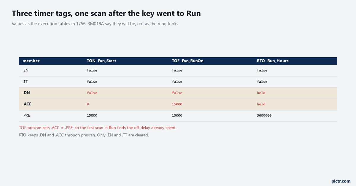
The TOF row is the one to look at. .ACC came out of prescan already at 15000, which is its own preset, so the timer is spent before your logic has run once.
The three false rows, in the order they bite
Take one rung condition and hang all three timers off it, then watch what each does.
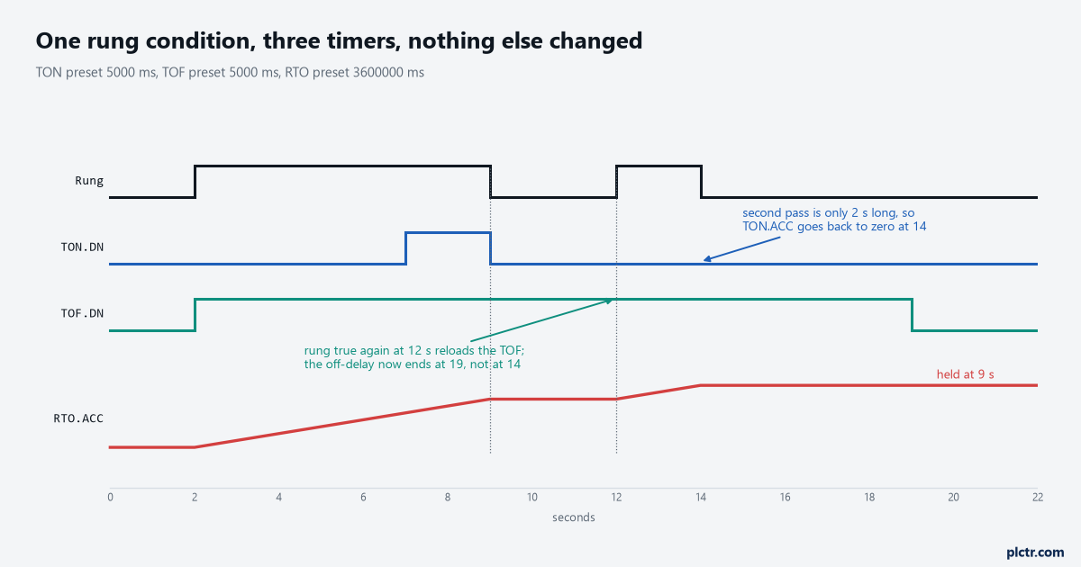
Same rung, same two presets. The TOF is high for seventeen of the twenty-two seconds and the TON is high for two, and neither of them is wrong.
The TON is the one everybody predicts. Rung true at two seconds, five second preset, .DN at seven, and when the rung drops at nine the whole timer goes back to zero — accumulator, done bit, timing bit. The second pass at twelve seconds only lasts two, so the TON never finishes and never will, because every interruption costs it everything it had. The RTO on the same rung keeps its seven seconds through the gap and adds two more, and the important half of that is not the accumulator. It is .DN. The RTO’s false row does not clear the done bit either, so a retentive timer that reached its preset stays done through the false rung, through a trip to Program mode and back, and through whatever the night shift did with the Clear Majors button. The TOF is the odd one, and it is odd in a specific way: the rung going true at twelve seconds is not a continuation of anything, it is a reset, and the off-delay that was going to expire at fourteen now expires at nineteen.
Nothing in that chart is a fault and nothing in it is configurable. It is the tables.
Retentive on Logix means retained through the rung and through a mode change. It means nothing at all about a power cycle, and that half of the argument — where the accumulator really goes when the volts drop, and which manual promises what — is worked through in timing a motor start with TON and RTO.
The whole table, because the corners are where the trouble is
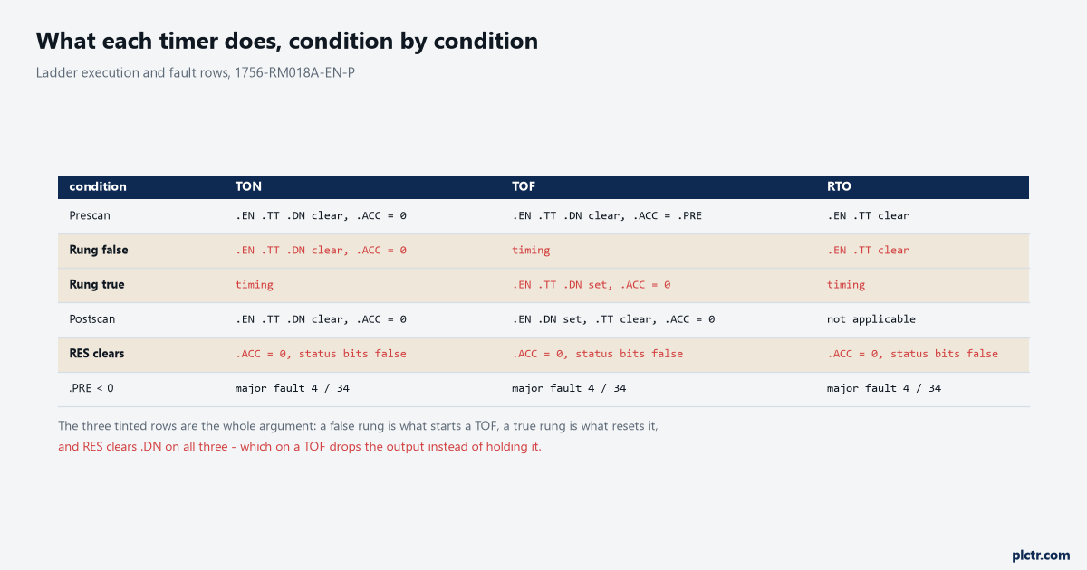
Six rows, three instructions. The tinted three are the ones that catch people; the other three are the ones everybody already knows.
Two entries in that table deserve more than a row each.
The first is postscan, which only matters if you are in SFC or calling routines from a phase, and which is where the TOF stops being symmetrical with anything. Postscan on a TOF sets .EN true, sets .DN true and clears .ACC — so a TOF inside a step that has just finished leaves its done bit set, and whatever that bit was driving stays energised until something scans the instruction again with a false rung. Postscan on a TON does the opposite and clears all four. If you have a routine that runs sometimes, the difference between those two rows is the difference between an output that latches on when the step ends and one that drops.
The second is the fault, and it is the same for all three.
A .PRE below zero is a major fault, type 4, code 34, and so is a negative .ACC. That sounds like a thing that cannot happen until you remember where presets come from on a machine with a recipe: an HMI numeric entry with no minimum, a copy that landed one element out and dropped a negative into a timer array, which is one of the ways CPT, CPS and COP bite on length, a subtraction in the rung above that went below zero on the first scan after a download. The controller does not clamp it and it does not warn. It faults, and you are in Program mode reading a code that 1756-PM014O no longer prints a table for — that manual now sends you to the Logix 5000 Controller Fault Codes spreadsheet in the knowledgebase, so the code-to-meaning lookup people used to do in the PDF is a download away.
Write the clamp yourself. One LIMIT on the preset before it lands in the timer costs nothing.
RES on a TOF does the opposite of what you want
Here is the one that reads like a bug report and is not.
An extraction fan runs on for fifteen seconds after the burner command drops, because that is what the burner manufacturer asked for. Somebody adds a RES on the fan timer, wired to the master reset, the way they would on any other timer in the project. Now the fan run-on works perfectly except when an operator presses reset while it is running, and then the fan stops instantly.
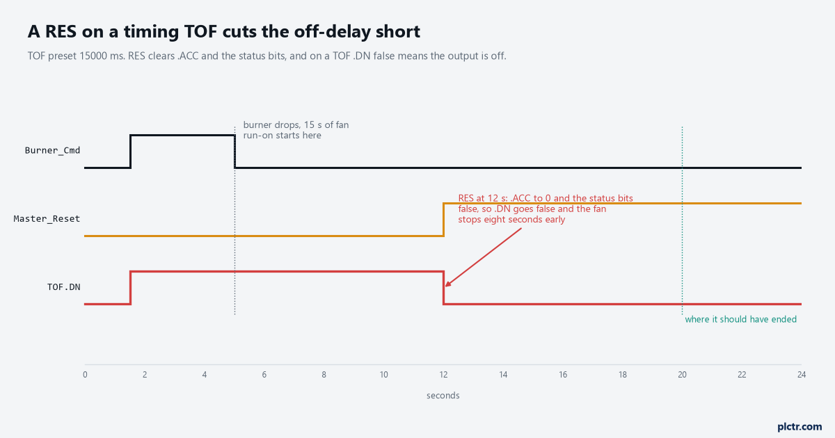
The RES did exactly what the manual says. On a TOF, clearing the status bits is what turns the output off.
The RES instruction clears .ACC to zero and the control status bits to false, and that sentence is written once in the manual for all three timers. On a TON or an RTO, false status bits mean not finished yet, which is what a reset should mean. On a TOF, .DN false means the off-delay has expired. Same instruction, same operation, opposite result, and the manual is aware of it: the entry for TOFR — the function block cousin with its own Reset pin — carries a note saying that its Reset sets .ACC = .PRE and that this is different from using a RES instruction on a TOF.
That note is in the manual because somebody hit this before you did.
So do not put a RES on a TOF. If you need the run-on to be abandonable, the thing you actually want is a second condition on whatever the done bit drives, not a reset on the timer.
And if you are writing in Structured Text or Function Block, the question does not come up, because RES is not available in either language and TOFR’s Reset pin is. That is a point in favour of the block version for anything with a reset in it: an unwired pin is visible on a printout and a missing RES in ladder is an absence, which is not.
The off-delay that never happens after a download
Back to the prescan row, because it is the one that costs the most time.
The pattern is a heartbeat. Something toggles a bit every second — a produced tag from another controller, a counter bit from an HMI, a bit a PC writes over CIP — and a TOF on that bit with a three second preset gives you a Comms_OK bit that is true while the toggling continues and false three seconds after it stops. It is a good pattern and it is everywhere. It also means that TOF.DN is the healthy state, and prescan sets .DN false.
So every download, every trip through Program mode, every controller power-up comes back with Comms_OK false, and it stays false until the first heartbeat edge arrives and drives the rung true.
Usually that is under a second and nobody notices. But if the permissive that bit feeds is latched somewhere downstream, or if the other controller’s heartbeat is slow, or if the line is interlocked to stop on Comms_OK false with no startup exemption, then the machine trips on every download and the fault log says a communication fault that never occurred. The fix is the same one that fixes most first-scan problems: gate the interlock with a startup mask driven off the first scan bit, which is the tool for exactly this and is covered in the PLC first scan bit.
The dead end here is worth naming because it is convincing. When a machine trips on every download, the network is the first thing anybody checks, and on a heartbeat-based health bit the network is genuinely a plausible cause. People go and look at connection counts and RPIs and the switch, and the switch is fine, and the connection never dropped. Nothing in the controller says the TOF started life spent. The tell is in the timing.
A real comms fault takes the full three seconds to appear. This one is already there on scan one.
What to look at next
Put the timer’s accumulator on a trend before you put it in a watch window. One scan of a false rung is invisible in a tag monitor and unmistakable as a sawtooth in a trend, and on a TOF the trend also shows you whether the rung is retriggering, which the done bit alone will not. Then go and find every write to the timer’s tag — not just the rung it sits on, but every instruction that touches .PRE, .ACC and .DN — because timing can be paused on a TON or an RTO by setting .DN true, and that is documented behaviour rather than an accident, so an HMI button bound one tag along will stop a timer dead while its rung sits there true and green. Cross-referencing the tag in Studio 5000 is how you get that list in thirty seconds. If the timer turns out to be fine and the argument is really about the preset, the arithmetic for choosing a number that will not nuisance-trip is in setting a conveyor jam timer from zone length and belt speed, and the plain instruction reference for the whole family is in timer and counter instructions.