PLC Bit Instructions XIO and XIC ladder examples
XIC and XIO instructions are one of the most used basic instructions in plc ladder programming. It is in the category of bit instruction and bit instructions can be used in input and output tags.

If you have a digital input, we can define and use these inputs in the PLC using the XIC instruction or XIO instruction, which is one of the bit instructions.
For example, let’s assume that you have one Limit Switch to keep in mind and design our PLC Program accordingly.
At the same time in our other inputs,
one stop button
one start button
one forward limit switch
one back limit switch
and we have one contactor.
Let’s write a motor start-stop program with these inputs.

Since all of our inputs are digital, we can use bit instructions in return. The difference between the XIC instruction and the XIO instruction, one is normally closed and the other is normally open contact. If we include the XIC instruction in our automation knowledge, we need to configure it to be active when external information such as start buttons is received.
The variables we will bind to the XIO instruction are, as I mentioned above if the variable/input comes continuously under normal conditions and we need to take action when it is interrupted. We need to evaluate the input we will determine accordingly with this instruction.
Start and Stop Instructions
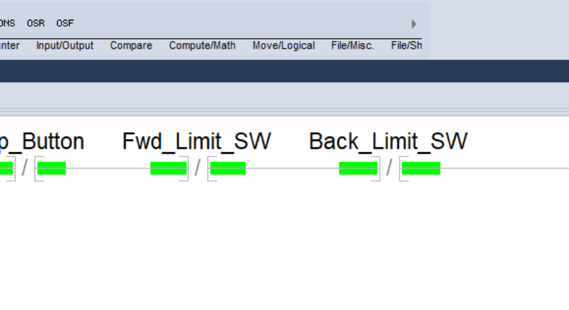
For example, in the stop command, the stop button already has a normally closed structure. Or we want our system to stop when the limit switches input is lost, that is, the cable is broken or the switch does not work. Therefore, it would be reasonable to evaluate these inputs in the XIO command. Of course, you must decide which commands you will choose according to the connection type of the element you will use. This means that your automation works correctly and completely. If you make the system stop by failing in case of any error and you will be on the safe side.
The XIC and XIO instructions should be evaluated as inputs., They become active according to the inputs from outside, and the plc enables the following instructions to be executed by energizing on the ladder. In the ladder diagram, there must always be an instruction after it, so it is always on the left side of the plc ladder diagram.
Let’s get to how our plc program should be,
PLC Instruction Example

Under normal conditions, when the start button and stop button are not pressed in the program. The motor contactor does not turn on as in the picture below.
The circuit latches itself over the motor contactor where you press the start button and the motor continues to run over. The motor contactor until you press the stop button or until the limit switches are activated.
