You have Studio 5000 installed, a ControlLogix or CompactLogix on the bench, and a blank screen. The next twenty minutes decide whether your first download works or ends in a firmware mismatch. This walkthrough is the exact sequence I use every time I create a project in Studio 5000, including the two settings people get wrong most often: controller revision and slot number.
Screens below are from Logix Designer v33. Menus have been the same since v21, so v30 to v36 users can follow along without surprises.
What you need before you start
| Item | Notes |
|---|---|
| Studio 5000 Logix Designer | Any version from v21 up. Your version must support the controller’s firmware major revision (v33 project → firmware 33.x). |
| Controller | Example here: 1756-L83E (ControlLogix 5580). A 5069-L320ER (CompactLogix 5380) works the same way, minus the chassis slot step. |
| RSLinx Classic or FactoryTalk Linx | Needed for the download in step 7. Set up in RSLinx configuration and connect to PLC. |
| Ethernet cable and IP address | Controller and laptop on the same subnet. If the controller is fresh, give it an IP first: Assign an IP address within Studio 5000. |
| No hardware yet? | Use Logix Emulate. See Studio 5000 Logix Emulate (virtual PLC). |
Check the controller’s firmware revision before you open Studio 5000. It is printed on the module display at power-up on 5580/5380 controllers, or visible in RSLinx under the controller icon, and you will need it in step 2. Write it down.
Step 1: Start a new Logix project
- Open Studio 5000. On the launcher click New Project.
- In the left column pick Logix. The right pane lists controller families: ControlLogix 5580, ControlLogix 5570, CompactLogix 5380, CompactLogix 5370, GuardLogix, Emulate.
- Expand the family and select the exact catalog number, for example 1756-L83E.
- Name: use letters, digits and underscores only, no spaces. Studio 5000 accepts 40 characters, but keep it short, because this name becomes the controller name that shows up in RSLinx and in every HMI tag path.
Line3_Filleris good.Line 3 filler (new)is a headache. - Location: the folder where the
.ACDfile lives. Put it somewhere backed up, because the ACD is the entire project and there is no separate source tree. - Click Next.
Step 2: Set revision, chassis and slot
This is the screen that causes most first-download failures.
- Revision: pick the major revision that matches the firmware on the controller. Firmware 33.011 means you choose 33. If the dropdown does not offer that number, your Studio 5000 install does not have that version and the project will not download until you either flash the controller or install the matching Logix Designer version.
- Security Authority: leave No Protection for a new project. You can add FactoryTalk Security later.
- Chassis type (ControlLogix only): pick the physical chassis, for example 1756-A7 for a 7-slot rack. Count the slots on the rack, do not guess.
- Slot: the slot number of the controller, counted from zero on the left, so a controller in the second position is slot 1. Get this wrong and the download will succeed but you will get an I/O fault the moment the controller looks for its own backplane position.
- Time synchronization: tick Enable Time Synchronization if you plan to use CIP Sync, motion, or timestamped inputs. Harmless to leave on.
- Click Finish. Studio 5000 builds the project and opens the Controller Organizer on the left.
Step 3: Know your way around the Controller Organizer
Three folders matter on day one:
- Controller holds Controller Tags (global) and Controller Fault Handler.
- Tasks holds
MainTask, which already containsMainProgramand an emptyMainRoutine; MainTask is a continuous task, so it runs the moment the previous scan ends. - I/O Configuration holds the backplane and the embedded Ethernet port, and at this stage it is empty except for the controller itself.
Everything else (Add-On Instructions, Data Types, Motion Groups) can wait.
Step 4: Add an I/O module
- In I/O Configuration, right-click 1756 Backplane (or the Ethernet port for remote I/O) and choose New Module.
- Type the catalog number in the filter, for example 1756-IB16, select it and click Create.
- Give it a Name (
Local_DI_Slot2), set the Slot to the physical position, and leave Electronic Keying on Compatible Module unless you have a reason to lock the exact revision. - Under Connection, the default RPI of 20 ms is fine for discrete I/O. Click OK.
The module now appears under the backplane and Studio 5000 creates its tags automatically: Local:2:I.Data.0 is input 0 on slot 2. Repeat for output cards. If the module you need is not in the list, the EDS file is missing; the fix is in EDS file installation via RSLinx. For drives and more detail on the module dialog, see adding a new module in Logix Designer.
Step 5: Create tags and write the first rung
Open MainRoutine by double-clicking it. Add a start/stop rung, the ladder equivalent of “hello world”:
Rung 0:
  ---] [---------]/[-----------( )---
    Start        Stop           Motor
   |
   ---] [---
     Motor
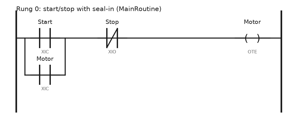
In plain words: XIC Start in parallel with XIC Motor, in series with XIO Stop, driving OTE Motor. The parallel Motor contact is the seal-in that keeps the motor running after the operator releases the start button.
Create the tags as you go: right-click the empty operand, choose New Tag, type BOOL, scope Program for now. To tie Start to a real input, make it an alias for Local:2:I.Data.0 instead of a base tag. Aliases keep your logic readable when the wiring changes.
If XIC and XIO are new to you, the examples in PLC bit instructions XIO and XIC cover the four combinations you will actually use.
Step 6: Verify
Menu Logic → Verify → Controller. The Errors window at the bottom must be empty. Typical first-timer errors:
Unknown tagmeans you typed an operand and never created the tag.Rung has no outputmeans you left a rung with contacts and no coil.
Fix them now. Studio 5000 will not download a project that fails verification.
Step 7: Set the path and download
- Menu Communications → Who Active.
- Expand your RSLinx driver (AB_ETHIP-1 for Ethernet), find the controller and select it. If it shows a yellow question mark, RSLinx has no EDS file for it, which does not block the download but will bother you later.
- Click Set Project Path, then Download.
- Read the confirmation dialog. It lists the project revision and the controller revision side by side, and if the two differ, stop and read the first field note below.
- After the download Studio 5000 asks whether to switch to Run mode. If the key switch on the controller is in REM, say yes; if it is in PROG, the controller stays in program mode until someone turns the key.
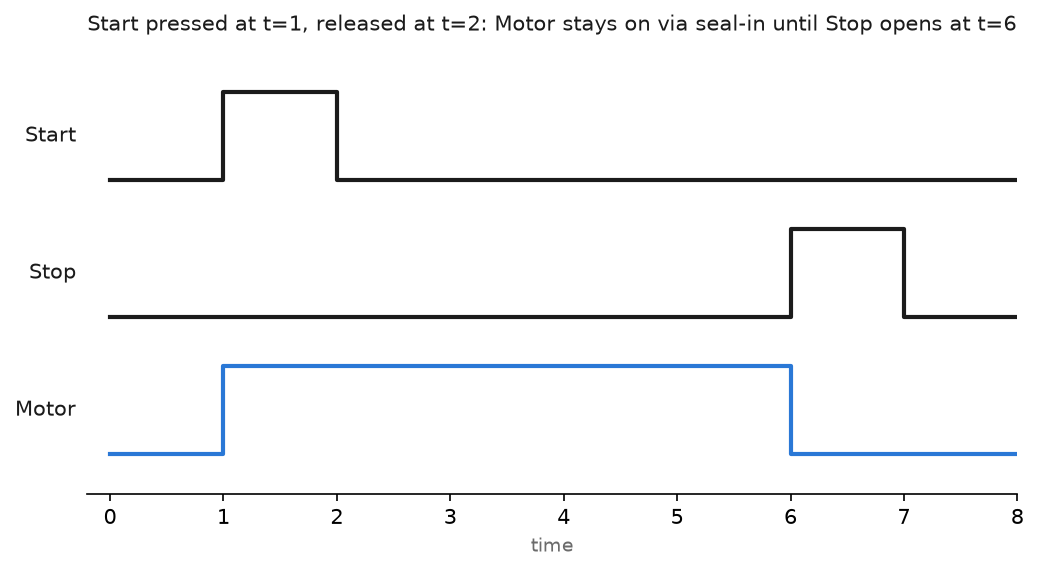
You are now online. The rung turns green where power flows. Toggle the Start alias by forcing the input or pressing the physical button, and watch Motor seal in.
Working without hardware? The same download works against an emulator, shown in downloading a program to the Studio 5000 emulator.
Field notes: what actually goes wrong
The revision mismatch. The download dialog says the controller is at 32.011 and the project is 33. Two ways out. Either flash the controller with ControlFLASH Plus to 33.x (needs the firmware kit from the Rockwell PCDC site and about ten minutes), or change the project: Controller Properties → General → Change Controller and pick revision 32. On a live machine I change the project, not the firmware. Flashing a controller during a shift is how you spend the night in the plant.
Slot 0 versus slot 1. A colleague created a project with the controller in slot 0, while the physical rack had the power supply in a separate housing and the controller in slot 1. Download went fine, then the controller reported I/O faults on every card because the backplane map was shifted by one. Symptom: solid red I/O LED, all modules faulted with code 16#0010. Fix: Controller Properties, change the slot, re-download.
Project opened in a newer version. Studio 5000 upgrades a v24 ACD to v33 silently when you open it in v33 and save. Your co-worker on v24 can no longer open it. Keep a copy before opening any project in a newer version, and use the version that matches the controller on the machine.
Name changes after the fact. Renaming the controller after the HMI is built breaks every tag path in FactoryTalk View. Pick the name in step 1 and leave it.
Frequently asked questions
Which Studio 5000 version do I need for my controller?
The project major revision must equal the firmware major revision: firmware 31.x needs Logix Designer v31, and 33.x needs v33. Several versions can be installed side by side; the launcher opens the right one for each ACD.
Can I create a project without a controller?
Yes. Choose Emulate 5570 as the controller type and run Logix Emulate on the same PC. Everything in steps 1 to 7 works the same, and you switch to the real controller later with Change Controller.
What is the difference between .ACD, .L5X and .L5K?
ACD is the working project, binary, opened only by Studio 5000. L5X (XML) and L5K (text) are exports you use for version control diffs, importing routines into another project, or sending a rung to a colleague, and you make either one from File → Save As by picking the type.
Do I have to add I/O before writing logic?
No. You can write everything with base tags and alias them to real I/O once the hardware arrives. This is normal on projects where the panel is built after the software.
Why is the Download button greyed out?
The path is not set, or you are already online, so use Who Active → Set Project Path first and go offline before downloading again.
Next step
Once the first rung runs, the next thing worth learning is Add-On Instructions in Studio 5000: they turn the start/stop rung above into a reusable block you can drop on every motor in the plant.