TAHH-301 at 150 C, voted 2oo3, closes the feed valve FV-301 and the steam valve SDV-310 and opens the quench XV-306. Not one of those four actions belongs in the controller that holds the jacket temperature, which is where the shape of this job comes from. PLC chemical process control on a real plant is split across three systems that must not lean on each other: the basic process control system, the safety instrumented system, and the package PLC that came bolted to the centrifuge skid. Get that split wrong and an HMI tag write can defeat an interlock. The example is a jacketed 8 m3 stirred reactor running an exothermic batch, and the sections cover the parts that cause arguments at HAZOP close-out.
Draw the line between BPCS, SIS and package PLC
| Layer | Typical hardware | What it owns | What it must not do |
|---|---|---|---|
| BPCS | DeltaV or Experion on the main train, ControlLogix 1756-L83E on package units | Regulatory loops, sequencing, recipe, operator alarms | Any SIL rated trip function |
| SIS | Triconex Tricon, HIMA HIMax, or GuardLogix 5580 for SIL 2 | De-energise to trip final elements, voting, proof test logging | Take a setpoint or permissive from the BPCS |
| Package PLC | CompactLogix 5380 or S7-1500 on the vendor skid | Skid interlocks, local drive control | Own the plant trip. It reports, the SIS trips |
IEC 61511 does not forbid a PLC in the SIS. It asks for independence, the right systematic capability, and a proof test you can actually carry out. A GuardLogix 5580 is rated SIL 2 alone and SIL 3 with the 1756-L8SP safety partner, so a SIL 2 reactor trip in a GuardLogix safety task is defensible. The same trip in the continuous task next to the recipe, in standard tags, is not.
The rule I hold to on site: data flows from the SIS to the BPCS and never back. The SIS produces status, first-out trip cause and health words, and the BPCS reads them over a read-only path, usually a CIP produced tag or a Modbus slave map with no writable coils. If the SIS needs a process permissive, wire the transmitter into the SIS rather than borrowing the BPCS reading.
Standards background: what is IEC 61508 and IEC 61511. Interlock construction: implementing PLC safety interlock systems.
Build the cause and effect matrix before you write a rung
The matrix is the contract between the process engineer and you. Everything in the safety task traces to one row; anything without a row does not belong there.
| Cause | Vote | Trip point | FV-301 feed | M-301 agitator | XV-306 quench | SDV-310 steam |
|---|---|---|---|---|---|---|
| TAHH-301 jacket outlet | 2oo3 | 150 C | Close | Keep running | Open | Close |
| PAHH-302 reactor head | 2oo2 | 6.0 bar g | Close | Keep running | Open | Close |
| LALL-305 reactor level | 1oo2 | 12 percent | Close | Stop | Inhibit | Close |
| M-301 run feedback lost | 1oo1 | 3 s filter | Close | n/a | Inhibit | Close |
| Gas detect cell 4 | 2oo3 | 20 percent LEL | Close | Keep running | Inhibit | Close |
Two rows catch people out. On high temperature the agitator keeps running, because stopping the mixer during an exotherm gives you hot spots and a worse runaway. On low level it stops, because a mixer run dry wrecks the seal. Write both down, otherwise the next engineer adds a blanket “all motors off” trip and creates a new hazard.
Loss of the agitator is itself a cause, since feed into an unmixed reactor is a classic runaway path. Run feedback comes from the drive status word, not a contactor auxiliary, with a 3 second filter for the restart dip.
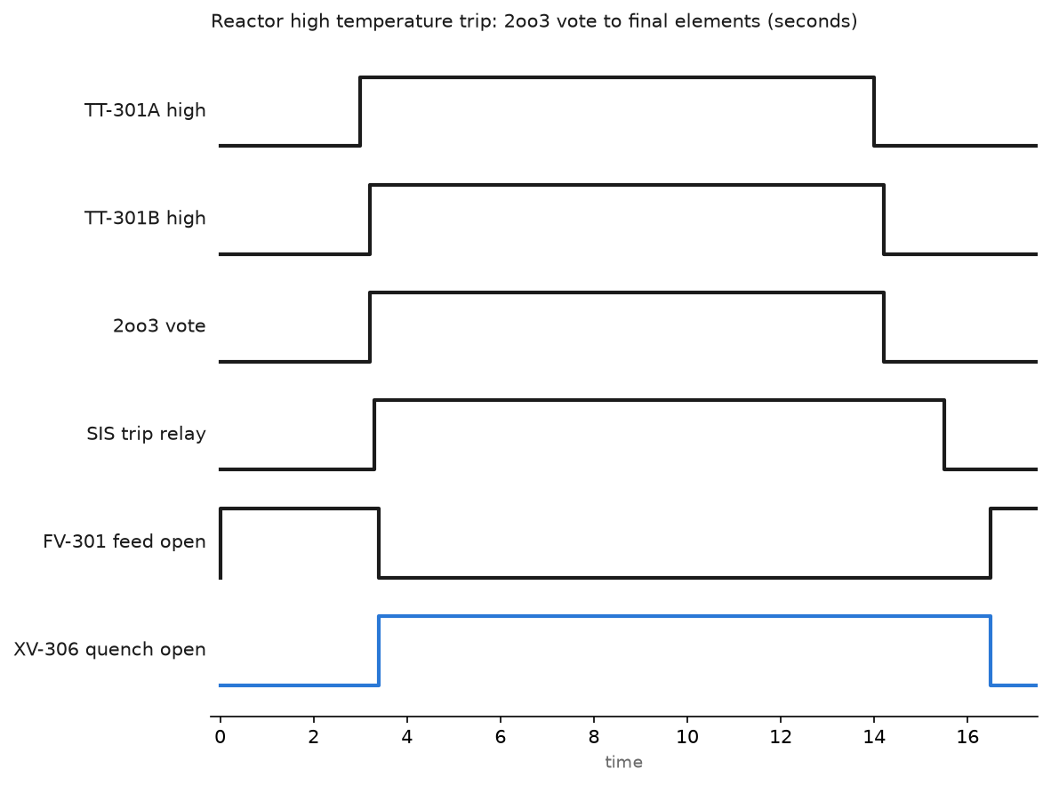
From vote to final element: one Tricon scan, set by the application and usually 50 to 100 ms, plus solenoid drop out and valve stroke. A 4 inch feed valve on a spring return actuator strokes in 2 to 4 seconds. Against a 20 second process safety time you have room. Against 5 seconds you need a quick exhaust valve, and that goes in the SIL verification.
Cascade the reactor temperature loop
A single PID on reactor temperature chases the exotherm and loses. Cascade splits the problem in two.
- Master loop TIC-301 reads reactor mass temperature and outputs a jacket setpoint in degrees.
- Slave loop TIC-302 reads jacket outlet temperature and drives a split range output.
- Split range: 52 to 100 percent opens steam valve TCV-302A, 0 to 48 percent opens cooling water valve TCV-302B. The dead band between 48 and 52 stops the pair fighting.
- Tune the slave first with the master in manual. The jacket loop is fast: integral near 60 seconds, derivative off.
- Tune the master four to six times slower. On this reactor it sits at gain 1.2, integral 10 minutes, derivative 30 seconds with a filter.
- Clamp the master output to a jacket setpoint the vessel can survive. Plus or minus 30 C around the batch setpoint is normal; the clamp is what protects a glass lining from thermal shock.
(* ReactorTemp, 500 ms periodic task, Studio 5000 v33, two PIDE blocks *)
(* master CVEU is scaled in degrees C and becomes the jacket setpoint *)

TIC301.SPProg := Recipe_Temp_SP;

Jacket_SP    := TIC301.CVEU;
Jacket_SP_Hi := (Jacket_SP > Recipe_Temp_SP + 30.0);
Jacket_SP_Lo := (Jacket_SP < Recipe_Temp_SP - 30.0);
IF Jacket_SP_Hi THEN Jacket_SP := Recipe_Temp_SP + 30.0; END_IF;
IF Jacket_SP_Lo THEN Jacket_SP := Recipe_Temp_SP - 30.0; END_IF;

TIC302.SPCascade := Jacket_SP;

(* stop the master integrating while the jacket loop cannot follow it *)
TIC301.WindupHIn := Jacket_SP_Hi OR TIC302.WindupHOut OR NOT TIC302.CasRatMode;
TIC301.WindupLIn := Jacket_SP_Lo OR TIC302.WindupLOut OR NOT TIC302.CasRatMode;

(* split range on the slave CV, 0 to 48 cooling, 52 to 100 steam *)
Steam_Cmd := (TIC302.CV - 52.0) * (100.0 / 48.0);
Cool_Cmd  := (48.0 - TIC302.CV) * (100.0 / 48.0);
IF Steam_Cmd < 0.0 THEN Steam_Cmd := 0.0; END_IF;
IF Cool_Cmd  < 0.0 THEN Cool_Cmd  := 0.0; END_IF;

IF NOT SIS_Trip_Healthy THEN
    Steam_Cmd := 0.0;   (* BPCS follows the SIS, it does not argue *)
END_IF;
The two Windup lines earn their keep. PIDE puts WindupHOut and WindupLOut on the slave for exactly this: fed into the master’s WindupHIn and WindupLIn, they stop the master integrating in the direction the jacket can no longer follow. Leave them unwired and the batch overshoots the moment cooling returns. PID mechanics: implementing PID control in PLC systems. Recipe handling: PLC batch process control.
Wire the hazardous area I/O the way the certificate says
Inside Zone 1 a loop is a certified system, not just 4-20 mA.
- Read the equipment certificate and the barrier datasheet side by side. Barrier Uo must be at or below transmitter Ui, Io below Ii, Po below Pi. An MTL5541 at Uo 28 V and Io 93 mA suits most two wire transmitters.
- Subtract the cable. Barrier Co and Lo minus cable capacitance and inductance has to stay positive. A 300 m run of IS cable at 120 pF per metre already uses 36 nF.
- Budget the voltage. An isolator like the MTL5541 powers the field loop itself and its datasheet quotes the voltage left at the terminals at 20 mA, around 16 V. Take off the cable drop and check the rest against the transmitter lift-off voltage, 10.5 V on a typical HART device. A Zener barrier is tighter, because its 300 ohm or so end-to-end and the 250 ohm sense resistor on the card both come out of the 24 V supply first.
- Keep the blue IS cable separate: 50 mm of air or an earthed divider inside the panel, separate glands, separate trunking.
- Earth the barrier busbar to IS earth through one dedicated conductor, under 1 ohm. A second bond in the field causes the fault in the notes below.
Rationalize the alarms against ISA-18.2
An alarm with no operator action is a log entry. On this reactor train we cut 640 configured alarms to 210 in two days with three questions per point: what does the operator do, how long do they have, what happens if they do nothing.
- Aim for around 150 alarms per day per operator, and treat 10 in 10 minutes as a flood.
- Give every analog alarm a deadband of 2 to 5 percent of span and an on delay of 3 to 10 seconds. That alone removed 40 percent of the chatter on the pressure points.
- Priority split near 80 percent low, 15 percent high, 5 percent urgent. When a third of the list is urgent, nothing is.
- Suppress by design rather than by shelving. Feed pump low flow means nothing while the pump is stopped, so gate it on the run bit. Put an 8 hour timer on anything shelved.
Alarm block state machine: PLC analog alarm state diagrams.
Field notes
The maintenance bypass that stayed in. A transmitter feeding PAHH-302 went for repair and the technician put the SIS maintenance override on that input. It stayed bypassed for 19 days, because the only indication was a small grey box on a detail page. The fix: an override active bit summed across the SIS, a hard annunciator on the main overview, and re-entry every 8 hours through a key switch that logs who did it.
Cascade windup after a steam header dip. The site header dropped from 9 to 5 bar during a compressor changeover. The jacket loop saturated, the master kept integrating, and when steam came back the batch overshot by 12 C and made off-spec product. Wiring the slave’s windup outputs into the master, as above, fixed it. The tell-tale on the trend: master output flat at 100 percent while jacket temperature never reached setpoint.
Three thermocouples in one thermowell. A 2oo3 vote had all three elements in a single well. The well fouled with polymer and all three read low together, exactly the common cause failure a vote exists to remove. They now sit in three nozzles at different heights. A vote is only as independent as its process connection.
IS earth bonded twice. A 4-20 mA level reading drifted by 0.3 mA whenever a 55 kW agitator drive ramped. The barrier busbar was bonded to IS earth in the marshalling cabinet and again to structural steel at a field junction box. Lifting the second bond removed the drift. Circulating current in an IS earth shows as a small offset that tracks the load, not as noise.
Frequently asked questions
Can I use a standard PLC for the shutdown if it is fast enough?
Speed is not the question. IEC 61511 asks for systematic capability and diagnostic coverage matched to the SIL, and evidence of both. A standard ControlLogix carries no certified claim for either. Use a safety controller, or hardwired trip relays for a small duty.
Should the SIS and the BPCS share transmitters?
Not for the trip. Separate transmitters, process connections and cards. Sharing is allowed under conditions, and proving them costs more than a second transmitter.
How do I test the interlocks before startup?
Inject at the transmitter with a loop calibrator rather than forcing a tag. Forcing proves the logic and nothing else. Record as-found trip point, as-left value and stroke time for every loop.
Next step
A reactor that trips every time a controller reboots is a hazard of its own, so settle BPCS redundancy next: implementing redundant PLC systems for safety critical applications. Then introduction to DCS and integration with PLC for how package PLCs hand data to the plant system.