A 20-750-S seated in port 4 of a PowerFlex 755, SP and SE landed on separate contacts of a 440R-D22R2, twenty-four volts measured on both pairs, and the drive faults the moment the contactor closes. The SAFETY enable jumper is still on the main control board, where it ships from the factory, and the manual is direct about the consequence: if that jumper is installed when a safety option is fitted, the drive will fault. Two jumpers decide whether this module is in the circuit at all, and only one of them comes out.
Safe Torque Off removes the ability to produce torque. It does that by killing the gate drive, not by opening anything, so the motor coasts, the drive stays connected to the line, and the terminals you would put a meter on are all still live. That is the whole of the function and the whole of its limit.
Everything below is the 20-750-S option module on a PowerFlex 753 or 755, with the numbers from Rockwell’s own safe torque off manual.
What the module actually switches
One sentence in chapter 3 carries the entire mechanism.
The option module disables the drive’s output IGBTs by disconnecting power to the gate control driver IC, or by disabling that driver’s output, which stops the output devices switching in the pattern that makes AC power for the motor. Nothing opens. No contactor drops, no bus is discharged, no phase is broken. Under normal running, 24 V sits on both the Safety Power and the Safety Enable inputs; de-energise either one and the gate firing stops, the HIM reports the drive as not enabled, and parameter 933 [Start Inhibits] tells you why — on a 755T product the same information is in 10:351 [M Start Inhibits]. The drive is then in its safe state, which the manual defines as preventing force-producing power from reaching the motor, with a caveat worth reading twice: the drive is in the safe state when the safety function is installed and the status reads Not Enabled, and Ready is not a safe state even when nothing is turning.
Ready with no motion looks identical from the platform. It is not the same state.
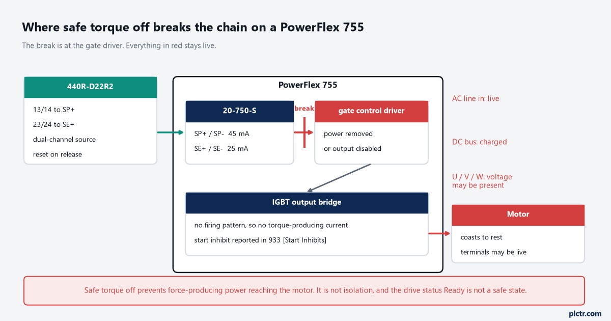
The break is at the gate driver, not in the power path. Everything drawn in red stays energised while safe torque off is active.
The two jumpers, and the fault that arrives on the first power-up
Both jumpers are on the main control board and they move in opposite directions.
The SAFETY enable jumper comes out, because it is what tells the drive there is no safety option; the hardware ENABLE jumper stays in. Leave the SAFETY jumper fitted with a 20-750-S installed and the drive faults, which is the failure above and takes about forty minutes to find if you are reading the wiring rather than the installation chapter. PowerFlex 755 control boards in frames 8 through 10 have no SAFETY enable jumper at all, so on those frames there is nothing to remove and nothing to blame. The module itself goes in any available port, with one exception that catches motion people: where the drive is an axis in an integrated motion application, the module has to be in port 6. Only one safety option module per drive; two of them, or a duplicate, is not supported. The retaining screws take 0.45 N·m (4.0 lb·in) with a T15 hexalobular bit, and they are the kind of screw that gets overtightened by somebody who has just been told the module is safety-related.
One jumper out, one jumper in, one module per drive.
The four terminals and the fifth wire that is not there
TB2 has six terminals and four of them do work.
SP+ and SP− are Safety Power, 24 V at 45 mA typical; SE+ and SE− are Safety Enable, 24 V at 25 mA typical; the two Sd terminals are the shield landing point when there is no EMC plate or conduit box. The supply is user-provided 24 V DC ±10%, PELV or SELV, and the module reads an input as on between 21.6 and 26.4 V and off below 5 V, drawing no more than 2.5 mA at 5 V in the off state. Cable is multi-conductor shielded, 0.3 to 0.8 mm² (28 to 18 AWG), stripped 10 mm, and the shielding is not optional decoration — it is how the wiring meets the EMC requirements the drive’s own installation instructions impose. Whole-module power consumption is 4.4 W. Both inputs have to be driven by proper dual-channel equipment for the full rating, and the manual says what happens when they are not: repeated activation of the safety function through one input at a time can produce a spurious fault.
The fifth wire is the one people go looking for and it does not exist. There is no safe-status output on the option module, so the bit the controller reads to know the guard circuit has dropped comes from the safety relay’s auxiliary contact or from the drive’s own start-inhibit parameter, never from TB2.
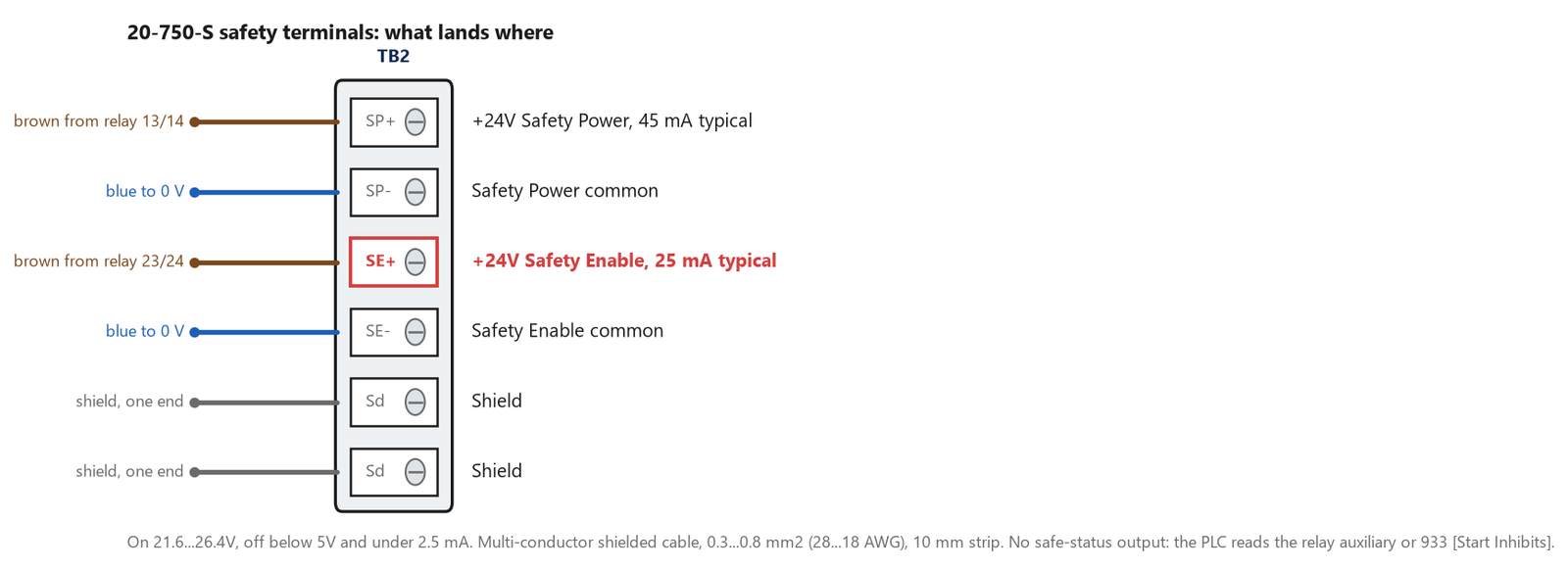
Six terminals, four connections, one shield. The status signal to the PLC comes from the relay, because the module has no output to give it.
What safe torque off does not do
This is the section to read before the commissioning test, because most of the trouble around STO is a correct function being asked to do a job it was never certified for.
It is not an isolation method. The manual states that the option module is suitable for performing mechanical work on the drive system or the affected area only, that it does not provide electrical safety, and that the module does not eliminate dangerous voltages at the drive output. Input power has to be removed and the usual procedures followed before electrical work, and the manual’s own attention notice adds that hazardous voltage may still be present at the motor while safe torque off is active, so the motor has to be disconnected and proved dead before anyone works on it. It is not a stop, either, in the sense a mechanical fitter means: by itself the module initiates a coast, which is a Stop Category 0 in the language of EN 60204-1, and where the application needs a different stopping action, additional protective measures are required. It does not hold a load. Where external influences such as a suspended load are present, the manual says further measures — a mechanical brake is the example it gives — can be necessary to prevent a hazard.
And it is not absolutely instantaneous in the way a contactor is. The safety reaction time, measured from the input condition that triggers a safe stop to the initiation of the configured stop type, is a maximum of 10 ms on some drive families and 20 ms on others, and an input condition present for less than that reaction time cannot result in the safety function being performed at all. Repeated requests shorter than the reaction time can produce a spurious fault. There is one more failure mode printed as an attention notice that deserves to be known by anyone who has ever put a hand near a spindle: if two output IGBTs fail while the module has commanded the outputs off, the drive can still provide energy for up to 180° of rotation in a two-pole motor before torque production ceases. That is a quarter turn of a shaft on a machine that a person believes is incapable of moving.
Nor is it a start and stop control. The manual says not to use the safety option module to start or stop the drive, and the reason is wear: every activation is a demand on a safety function whose data assumes a demand rate, not a duty cycle.
One more gap is honest and easy to miss. If an external fault sits on the wiring or the circuitry controlling the Safety Enable or Safety Power inputs for a period of time, the module does not detect it, and when the external fault clears the module allows an enable condition again. The diagnostics live in the device driving those inputs — the relay, the safety controller, the Guard I/O module — which is exactly why the contacts on the far end have to be a rated dual-channel source rather than two auxiliary contacts off a starter.
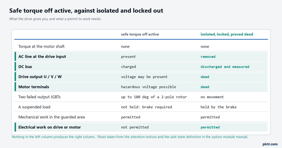
The left column is what the drive gives you. The right column is what a permit to work needs, and nothing in the left column produces it.
When a coast is not an acceptable stop
A Stop Category 1 is the answer and it takes a second output.
The manual’s own example does it with a 440R-D22R2 and a 440R-EM4R2D delayed expansion module: opening the guard switches the relay’s input circuits, the immediate outputs 13 and 14 issue a stop command to the drive so it decelerates under control, and after the set delay the timed outputs 17, 18 and 27, 28 trip the safe torque off inputs and the drive enable. If the motor is still turning when the timed contacts open, it coasts from wherever it has got to — which is the point of choosing the delay from a measured deceleration rather than from a round number. A single detected fault on the relay’s safety input circuits locks the system out at the next operation without losing the safety function, and there is a neat detail in the summary table for the other direction: if the safety option module sticks on, the motor still stops on command through the enable input, and the system cannot be reset while that fault condition exists.
Time the delay with a trend of actual speed, not with a stopwatch and an opinion.
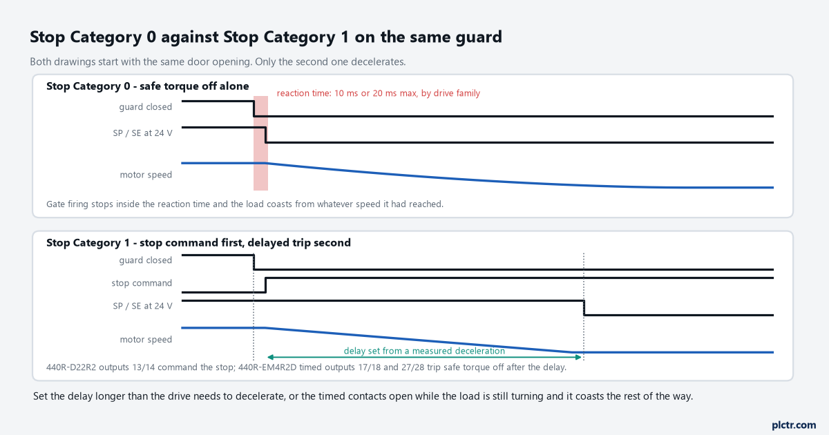
Set the delay longer than the measured deceleration. Short it and the timed contacts open while the load is still turning, and the last part of the stop is a coast again.
The numbers, and where the manual disagrees with itself
The safety data is printed per drive family and per frame, and it is worth copying into the file rather than quoting a level from memory.
For a PowerFlex 753 or a PowerFlex 755 in frames 1 through 7 the module is listed at PFDavg 3.29E-5 and PFH 3.75E-10 per hour, SIL 3, PL e, Category 3, MTTFD of 143 years, DCavg 99% (high), hardware fault tolerance 1 in a 1oo2 arrangement, and a 20-year mission time. Frames 8, 9 and 10 carry their own rows with numbers an order of magnitude different, which is the sort of thing a safety file gets wrong when somebody copies the first row of a table. Then there is a genuine inconsistency to be aware of: chapter 1 certifies the module for PL e and Category 3 to EN ISO 13849-1, while the general specification table in appendix A lists Cat. 4 and PL e when used with PowerFlex 750-Series drives and Cat. 3 and PL e with TotalFORCE products. The per-frame safety data tables all say Category 3 with HFT 1, and that is the pair of numbers I would put in a calculation and defend.
Take the row for your frame. Not the row at the top of the table.
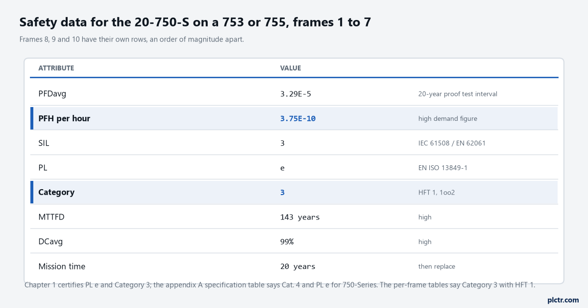
These are the module’s figures alone. The function they belong to still has a device at one end and a risk assessment behind it.
Before it counts as a safety function
The module is one subsystem of something larger, and the manual is explicit about who owns the rest.
The system user is responsible for the risk assessment and for reassessing whenever anything changes, for the rating and validation of the sensors and actuators connected to the system, for certification to the level the assessment requires, and for proof testing at intervals that the analysis sets rather than a calendar. Operation has to be verified after installation and after any modification or maintenance, and both channels checked rather than one. There is an environmental condition that catches retrofits into older cabinets: a product with a safety function has to be protected against conductive contamination, which means an enclosure of at least IP54 or NEMA/UL Type 12, or a controlled location, and failing to hold the specified ambient temperature can itself cause a failure of the safety function. For the wider path from a risk assessment to a level, the functional safety article is the companion piece, and the dual-channel E-stop write-up covers the device end of the same circuit. If the drive itself is new to the project, adding a PowerFlex to a Studio 5000 project and the motor control and VFD setup notes cover the non-safety half, and the motion control article is the one to read before you commit the drive to an axis and lose port 6.
Next step: with the machine safe, open one channel at a time and watch 933 [Start Inhibits]. If the drive inhibits on either channel alone and reports a fault when the same channel is cycled repeatedly, the module is wired the way its manual expects — and that test, written down and dated, is the start of the proof-test record rather than the end of the commissioning.