Omron PLC CX-Programmer – I/O Table Creation
How easy it is to automatically create an i/o table in CX programmer the i/o table is a snapshot of the i/o and communication modules on a CPU bus and associated configurations and settings.
Right now I have a CX program or project file open that is empty of any settings
To create an I/O Table, first of all, create a new project and select the Proper PLC CPU accordingly. After that on the left-hand side in the Project workspace, you will see an option of “I/O Tab & Unit Set up”, double click on it to Open. Here select the Main Rack and then In the options tab click on Create. This Will create the I/O table and will transfer all the connected I/O Units with PLC in the I/O table.
After the creation of the I/O table, you will see that all connected Units with CPU will be displayed here in this section. After that click on Verify and we are done with the I/O table Part.
Important Note:- The I/O Table will only create if the PLC is Online and we have to be in Program / Stop Mode while creating the I/O Table.
In the programming, we’re going to create the i/o table so we can start programming a new application let’s get started.
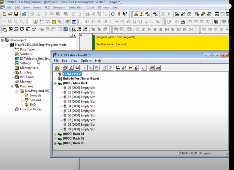
to view, the i/o table simply double-click the i/o table and unit setup item in the project tree.

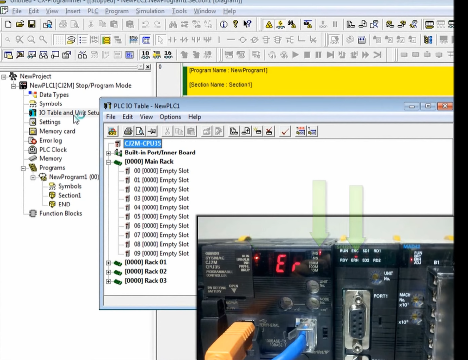
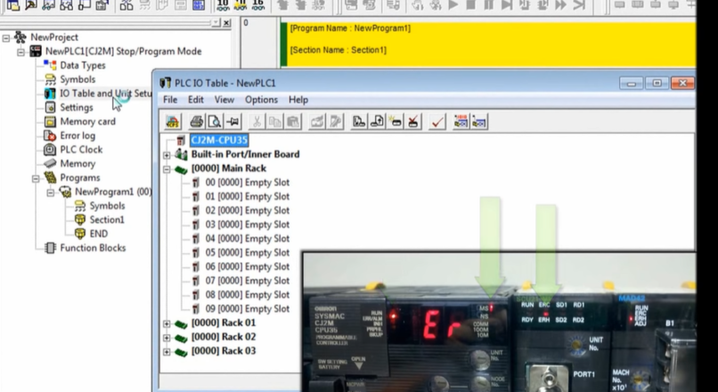
Status LEDs and Error Conditions
Notice that the main rack currently shows no modules attached to the PLC. CPU programmer is showing an error condition. Also notice in the picture on the bottom right the CPU and two modules are showing error conditions indicated by the red LEDs. This indicates that there’s a problem due to not having an i/o table.
Transfer I/O Tables and Settings
The rack consists of a CPU 21 serial module a mixed i/o analog module, a relay output module, and an AC input module to fix this problem we’re going to create the i/o table. First to make sure that the main rack is selected then select options, create. Select yes to confirm that you’d like to create an i/o table. Select yes to initialize the CPU bus settings. This will clear out any module settings. That may exist from previous applications. Make sure both IO table and SiO unit parameters are selected. This will allow CX programmer to upload the i/o table and special i/o settings.
 After the i/o table is created.
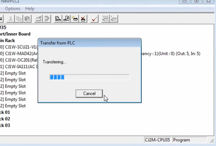 now press the transfer button after a few seconds the transfer results in the dialog box will be displayed showing the result of our i/o table creation in this case we created our i/o table that contains our modules module 0 is the seu 21 serial module 1 is the maad 42 mixed io module 2 is the OC 201 relay output module and MA three is the ia 111 AC input module
 also notice that the plc CPU and each module no longer display error conditions as you can see it’s very easy to create an IO table and CX programmer.