Fifty to a hundred PIDE loops on a 1756-L83E before scan time starts to hurt. Two to three hundred on a DeltaV MD Plus, where each loop comes out of a library with its alarm and its historian entry already attached. That gap is what PLC vs DCS programming costs you in practice: on Logix you write the logic and then own the scaling and the faceplate for every point you add, and the HMI is a separate project on top. On DeltaV or PCS 7 one change updates the controller database and the operator graphic together. It decides the engineering hours, and it decides who can fix the plant a year later.
Examples below use Studio 5000 v33 with a 1756-L83E, Emerson DeltaV v14 and Siemens PCS 7 V9.
What you are actually choosing between
| Family | Typical controller | Engineering tool | Where you meet it |
|---|---|---|---|
| PLC, tag based | 1756-L83E, 5069-L320ER | Studio 5000 Logix Designer | Packaging, conveyors, machine skids, water plants |
| PLC, symbol based | S7-1516-3 PN/DP | TIA Portal | European OEM machines – mixed process and discrete |
| DCS, loop centric | DeltaV MD Plus, MQ | DeltaV Explorer and Control Studio | Chemicals, pharma, pulp mills, refineries |
| DCS on S7 hardware | S7-400H, S7-410 | PCS 7 Engineering System, CFC and SFC editors | Large Siemens process plants |
| DCS, unit operation | Experion C300 | Control Builder | Oil and gas, gas processing |
Look at the third column. On the PLC side the HMI is a separate project. On the DCS side the controller database, the graphics and the historian belong to one project, and adding a loop updates all three at once.
The programming model is the first real difference
A Logix project is a tag database plus routines. You create LT101_PV as a REAL, you write a rung or a line of Structured Text that fills it, and nothing else in the system knows what that tag means beyond your naming convention.
A DCS project is a set of module instances. In DeltaV you place an AI block and a PID block inside a control module named TK101/LIC101. The AI block already carries XD_SCALE, OUT_SCALE, PV_FTIME, SIMULATE and its own alarm parameters. The historian collects LIC101/PV.CV because the block told it to. The faceplate exists because the module class has one. Cascade, ratio and feedforward arrangements are block wiring on the same sheet; on Logix they are PIDE instructions you chain by hand.
Here is the same analog input handled on the Logix side, written in Structured Text so you can see the volume of code that a DCS block replaces.
(* Logix: one 4-20 mA level input, done properly. You write all of this. *)
LT101_Raw := Local:3:I.Ch0Data;                      (* raw counts, 4000 to 20000 here *)
LT101_PV  := (LT101_Raw - 4000.0) * (100.0 / 16000.0);

(* wire break and over range, because the card only flags the extremes *)
IF LT101_Raw < 3600 OR LT101_Raw > 20800 THEN
    LT101_Bad := 1;
ELSE
    LT101_Bad := 0;
END_IF;

(* HI alarm, 2 percent deadband, 3 second on-delay *)
IF LT101_PV > 85.0 THEN LT101_HI_Raw := 1; END_IF;
IF LT101_PV < 83.0 THEN LT101_HI_Raw := 0; END_IF;

LT101_HI_Dly.PRE         := 3000;
LT101_HI_Dly.TimerEnable := LT101_HI_Raw AND NOT LT101_Bad;
TONR(LT101_HI_Dly);
LT101_HI := LT101_HI_Dly.DN;
A dozen lines for one instrument, and a 1756-IF8 or 5069-IF8 that hands you a scaled REAL only removes the first two. Multiply by 400 analog points and you see why process people reach for a DCS. In DeltaV the same behaviour is four parameters on the AI block: HI_LIM, HI_PRI, ALARM_HYS and the alarm delay. In PCS 7 it is a CFC sheet with a MonAnL block from the Advanced Process Library wired to the channel driver.
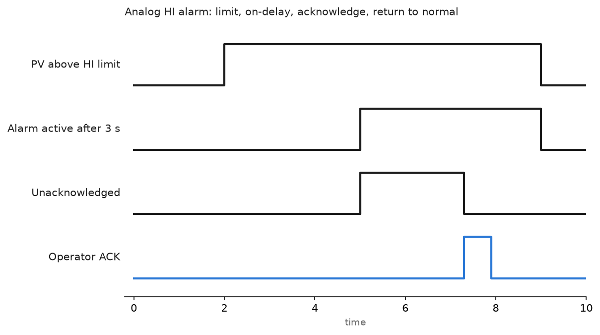
Both systems need that chart. On a DCS it is configuration; on a PLC it is code you test once and copy correctly 399 more times. Add-On Instructions close most of the gap. The PlantPAx process library, P_AIn and P_PIDE in the 4.x releases and native process instructions from PlantPAx 5.0 on, exists for exactly this, and it is the right answer when you stay on Logix for a process job. Building your own is covered in Studio 5000 Add-On Instructions.
Where the differences bite on a real project
| Topic | PLC, Logix or TIA | DCS, DeltaV, PCS 7, Experion |
|---|---|---|
| Primary language | Ladder; ST and FBD as needed | Function blocks on a wired sheet, SFC for sequences |
| Loop density | Rule of thumb, 50 to 100 PIDE loops per controller before scan time hurts | 200 to 300 loops per controller is normal |
| Redundancy | Second chassis, 1756-RM2 pair, periodic tasks only | Paired controllers out of the box, switchover in one execution period |
| Online changes | Edit a rung online, test, assemble. Large edits are risky | Download one module while the rest keeps running |
| Alarms | You write them and map them to the alarm server | Inside the block; priority and ack model follows ISA-18.2 |
| History | Configure a datalog or an external historian | Enable a parameter |
| Batch | S88 phases you build yourself | DeltaV Batch or SIMATIC BATCH, recipes and phase logic included |
| First cost | Low. A CompactLogix and a PanelView is a few thousand | High. Six figures before the first loop runs |
| Who maintains it | Any controls technician with the ACD file | Someone trained on that specific DCS |
Scan behaviour is the part that surprises PLC people. A Logix continuous task runs as fast as it can, so a badly organised process program gets a 60 ms scan and a jittery loop. A DeltaV or PCS 7 controller runs everything on fixed execution periods, typically 100 ms, 500 ms or 1 s per module, with an explicit execution order. Tuning numbers from a DCS do not transfer to a PLC unless you match the sample period first. If you are moving loops across, read implementing PID control in PLC systems and pin the periodic task period before you touch the gains.
Redundancy is bought on one side and designed on the other
On a redundant ControlLogix you buy two chassis, two 1756-RM2 modules and a fibre link, and then you find out what the crossload does not cover. MSG instructions in flight are lost. Logic that depends on a one shot straddling the switchover scan misbehaves. The crossload itself adds to scan time, and Rockwell wants the whole program in periodic tasks with no continuous task. You prove it by pulling the primary while the machine runs.
On a DeltaV MQ pair or an S7-400H the switchover is the vendor’s problem. The standby runs the same program against the same data, and the swap is bumpless because the hardware keeps the memory images in step. You still test it, and you rarely find logic that breaks.
PLC-only redundancy is worked through in implementing redundant PLC systems.
Alarm management is where migrations go wrong
A DCS gives you the ISA-18.2 model without asking: priority, state, shelving, suppression by design, and alarm history that survives a controller restart. TK101/LIC101/HI_ALM is unique across the plant because the module name is part of it.
On a PLC you build that yourself. Logix gives you ALMD and ALMA instructions that publish to the FactoryTalk alarm server. The trap is mixing methods: ALMD here and plain BOOLs polled by the HMI there, so nothing shares a timestamp source and the alarm summary cannot be sorted by time. Pick one method on day one. The instruction set is covered in PLC alarm instructions and analog alarms with ALMA.
Batch settles the argument more often than loop count does
If the plant makes recipes, the DCS case usually wins on its own. DeltaV Batch and SIMATIC BATCH implement ISA-88 as a product: recipe editor, phase logic interface, batch history, electronic records for a regulated site. Equivalent phase logic in Logix is possible and people ship it, using PhaseManager with FactoryTalk Batch, but that integration is a project rather than a checkbox.
Three mixers and a fixed product list, PLC phase logic is fine. A pharma site with 40 recipes and an auditor, it is not close. The PLC side of that work is in using PLC for batch process control.
How to pick without a vendor in the room
Count four things.
- Analog loops. Under 30 and mostly on-off, take the PLC. Over 150 continuous loops, the DCS engineering hours pay for themselves.
- Recipes. A real S88 requirement pushes you to a DCS or to a serious batch add-on.
- Who fixes it at 3 a.m. A site with two DCS trained engineers and thirty electricians has already answered the question.
- How often the process changes. A packaging line rebuilt twice a year is miserable on a DCS.
Hybrid plants are the common case now: DCS on the process, Logix or S7 on the packaging end, tied together with OPC UA or Modbus TCP. The gateway details are in DCS and PLC integration.
Field notes: what actually goes wrong
The 180 rung copy and paste. A team converted a small DCS unit to CompactLogix and copied the analog handling rungs 180 times with find and replace. Three inputs kept the wrong scale factor because the source was 0 to 10 V rather than 4 to 20 mA. An operator found it two months later, not the logic. On a DCS the scale is a parameter you can list in one table. On a PLC, build an AOI and pass the range in as an input.
Scan time killed the tuning. A loop moved from a PCS 7 CFC running at 200 ms into a Logix continuous task. It oscillated. The gains were right, the sample period was not: the continuous task ran at 14 ms one minute and 70 ms the next, and the derivative term chased the jitter. Moving the loop into a 200 ms periodic task with the same gains settled it in one shift.
Frequently asked questions
Is a DCS just a PLC with better software?
The controllers are close now. The difference is the engineering database. A DCS ties controller, graphics, alarms and history to one object, so one change updates everything. A PLC leaves that job to you.
What about safety systems?
Neither answer changes the safety layer. SIL rated logic runs on GuardLogix, a DeltaV SIS node or an S7-400F, separate from the basic process control system.
Do I need a DCS for 60 loops?
Usually not. Sixty loops on a 1756-L85E with the process library, PIDE in periodic tasks and a FactoryTalk View SE server is a normal project. You pay in engineering standards rather than licences. Revisit the decision if recipes or regulated records enter the scope.
Next step
If you are on the PLC side and the process content keeps growing, standardise before the tag count does. Build one analog input AOI and one loop AOI and force every point through them. Start from Allen-Bradley function block programming, then feed the result to a historian with the method in OPC for PLC integration.