The Kinetix 5700 Power Rail: What Each Module Is, and the Order They Go In
A 2198-D032-ERS4 is 55 mm wide, a 2198-S160-ERS4 is 100 mm, and the DC-bus link that joins one module to the next is a moulded part in a fixed length that arrives in the box with the module. There is no adjustment in it. Lay a rail out by eye, drill the subpanel, hang the modules, and the third link comes up short of the connector it is supposed to reach — at which point the only fix is a second set of holes.
The order is not free, and it is not enforced by the software either. Put the 2198-Pxxx or 2198-RPxxx supply at one end, run the inverters away from it by power rating with the biggest one nearest the supply, and put the accessory modules on the outside of the cluster. Then check the one rule that is genuinely directional: the 24V control bus only ever extends left to right, whichever end the DC-bus supply sits at.
Everything below is a single-cluster Kinetix 5700 system on one subpanel, from the Kinetix 5700 Servo Drives User Manual, publication 2198-UM002.
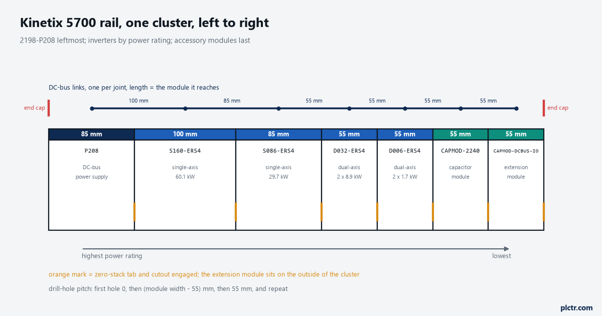
The link above each joint is the part that fails a sloppy layout. Its length is set by the module spacing, and the module spacing is set by the holes you drilled.
What is actually bolted to the rail
There are four kinds of thing on a Kinetix 5700 rail and most panels only carry three of them.
The 2198-Pxxx DC-bus power supply is a converter: three-phase AC in, DC bus out, nothing else. It has no motor connector. Most systems have one, and the manual allows up to three in parallel to raise converter power, with the condition that two or three supplies wired into the same cluster must all be catalog number 2198-P208. The 2198-RPxxx regenerative bus supply does the same job for applications in the 24 to 140 kW range and puts braking energy back into the line instead of into a resistor. The 2198-Sxxx-ERSx single-axis inverters and 2198-Dxxx-ERSx dual-axis inverters are the parts with motors on them; a 2198-S086-ERS4 is rated 29.7 kW continuous and a 2198-S312-ERS4 is 112 kW, while the dual-axis family runs from 2 × 1.7 kW on a 2198-D006 to 2 × 15.9 kW on a 2198-D057. The -ERS3 and -ERS4 suffix is a safety distinction, not a power one: the power structure is the same, and -ERS4 adds Monitored SS1 and the controller-based safe stop and safe monitor functions over the network.
Then the three accessory modules, all 55 mm wide, all rated 104 A on their own.
2198-CAPMOD-2240, the capacitor module, is 2240 µF of energy storage, the connection point for an external active shunt, and the way the DC bus gets out of the cluster to another one. 2198-CAPMOD-DCBUS-IO, the extension module, is the part that takes an extended cluster past 104 A: it pairs with a capacitor or conditioner module and carries the flexible bus bars in the box, and two accessory modules joined that way handle up to 208 A. 2198-DCBUSCOND-RP312, the conditioner module, reduces the voltage stress that long motor cable puts on inverter insulation, and a regenerative system needs one on every extended cluster and one on the power supply cluster as soon as that cluster’s motor cable total reaches 400 m.
A capacitor module is not optional decoration when the load steps hard. It is also 2240 µF you have to account for.
Where the supply goes, and which way the inverters run
The manual is looser here than people expect, and that looseness is where the arguments start.
The DC-bus power supply or regenerative bus supply can be mounted at the far right, the far left, or anywhere in between, and the manual says plainly that you should pick whichever makes the best use of panel space. It then adds one preference that most people miss, in the drill-hole section rather than the mounting section: the far left position is preferred, because it suits the 24V shared bus. Inverter modules and iTRAK power supplies get mounted in order from left to right or from right to left, and the recommendation printed alongside it is to order them by power rating, highest to lowest, starting with the highest next to the supply. That is a recommendation, and Logix Designer will not stop you doing otherwise. What Logix Designer enforces is the shared-bus configuration — Bus Configuration set to Shared AC/DC on the converter and Shared DC on the inverters, and every module on one physical bus bar assigned to one Bus Sharing Group. It has no idea what order the hardware is in.
Accessory modules are the exception here: they carry real placement rules, not preferences.
The extension module is always positioned on the outside of a cluster, first or last, and always next to a capacitor module or a DC-bus conditioner module. Mount two accessory modules side by side and they must be joined by the two flexible bus bars, which only ship with the extension module — put two capacitor modules together, or a capacitor module and a conditioner module, and you need the 2198-KITCON-CAPMOD2240 or 2198-KITCON-DCBUSCOND connector set ordered separately. On a regenerative system the conditioner module goes on the far right or far left of the cluster, depending on the input power configuration.
The trap that costs a day is quieter than any of that. A drive cluster laid out right to left is a perfectly legal Kinetix 5700 system, and the DC bus does not care which way the current runs along the bars. The 24V bus does.
The 24V bus has a direction; the DC bus does not
The 24V control power shared-bus system is optional, and when you use it the manual states its direction twice, in two different chapters, because it catches people.
It always feeds 24V DC from left to right. The input wiring connector — 2198-TCON-24VDCIN36 for the supplies and the capacitor module — plugs into the leftmost module that is fed by the external 24V, and T-connectors with bus bars in 55, 85, 100 and 220 mm carry it along the rail from there. The output current from that 24V supply must not exceed 40 A. If your own arithmetic says you will pass 40 A, the manual allows a second input wiring connector inserted anywhere mid-cluster to begin a new 24V bus — and then repeats that the input connector must always extend the bus from left to right. So a rail with the servo supply on the right still takes its 24V feed at the left-hand end, and the panel builder who mirrors the whole layout to suit the door hinge discovers this with the connector already crimped.
Count the current before you size the supply, because the numbers are not small.
A 2198-P208 draws 1.9 A of 24V on its own. Each single-axis inverter from the 2198-S086 up to the 2198-S312 draws 4.6 A, a 2198-D057 draws 2.3 A, and the smaller dual-axis inverters draw 1.4 A, all before any motor brake current is added on top. The worked example in Appendix C reaches 22.9 A on a rail of one 2198-RP312, two 2198-S312-ERS4 and two 2198-D057-ERS4 — and then shows that 22.9 A down 21.3 m of 1.5 mm² wire drops 6.43 V and lands 17.57 V at the drive, which is nowhere near the 21.6 to 26.4 V the input needs. Going to 6 mm² brings the drop to 1.60 V and the applied voltage to 22.40 V. That is a wire gauge problem masquerading as a drive fault, and it shows up as modules that will not finish their startup sequence at the far end of the rail. If you are sizing the panel’s 24V supply for the first time, the way a panel 24 VDC supply behaves under load and on a dip is worth reading alongside the drive numbers.
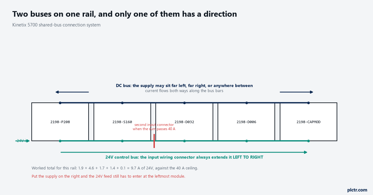
The DC bus is symmetric and the 24V bus is not. Mirror a layout to suit the enclosure and only one of these two survives the change.
The holes decide the layout, not the modules
Zero-stack is the reason the drill-hole arithmetic matters, and it is stated as a requirement rather than a suggestion.
Engaging the zero-stack tab and cutout from module to module is required for any input power configuration, and the reason given is exactly the one you would guess: it is what holds the DC-bus connectors at the spacing the shared-bus connection system expects. Get the holes wrong and the tabs will not seat, and if the tabs will not seat the links will not reach. The horizontal pattern comes out of a four-step rule that fits on a Post-it: the first hole is at zero, the second is at the module width minus 55 mm, the next is at 55 mm, and you repeat those two for the rest of the rail. Vertical hole positions differ by module, so the lower hole for a 2198-P031 is not the lower hole for a 2198-S160. The manual also notes that hole spacing is given in millimetres and deliberately not converted to inches, to keep rounding out of it — which tells you how much slack there is.
There is a 2198-K5700-MOUNTKIT system mounting toolkit that does the positioning for you. On a rail of more than four modules it pays for itself the first time.
DC-bus links latch on both sides when they go in, and to get one out again you depress both sets of upper pivots to release the lower pivots and pull upward while holding the link firmly. End caps go into the exposed DC-bus connectors on the first and last module of the cluster, and they are not optional cosmetics — they are covering live bus.
A link that will not reach is a hole somebody drilled in the wrong place.
What each module costs the rail
Every module you hang adds three numbers to three running totals, and none of the three is totalled for you anywhere in the software.
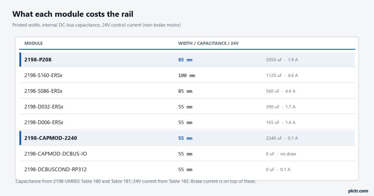
Three running totals: panel width, DC-bus capacitance against the supply’s ceiling, and 24V current against 40 A. The software keeps none of them.
The capacitance column is the one that decides how many inverters a supply will carry. A 2198-P208 supports 13,000 µF of total system capacitance and brings 2050 µF of its own to the total; a 2198-P031 or 2198-P070 supports 8000 µF. The worked seven-module rail in Appendix C — a 2198-P208, a 2198-S160, a 2198-S086, two 2198-D020 and two 2198-D006 — sums to 4840 µF, which is comfortable. Add two capacitor modules for ride-through and you have spent another 4480 µF of the ceiling without adding an axis. Width is the second total, and on a rail where every inverter is 55 mm it is easy to forget that a single 2198-S160-ERS4 is nearly two of them.
Two capacitor modules spend more of that ceiling than four dual-axis inverters do.
Before you drill
Write the rail out as a list before anything goes on the panel: catalogue number, width, internal capacitance, 24V current, one line per module. Sum the three columns. Check the capacitance against the supply you chose and the 24V against 40 A, then run the drill-hole rule from the left-hand module and mark every hole before the first one is cut. If the sums say the supply is short, that decision is cheaper now than after the bus bars are in.
With the rail laid out, the next thing that bites is the project side: adding a drive to the I/O tree in Logix Designer is where the Bus Sharing Group gets set, and a Kinetix 5700 axis and its first MAM move is where you find out whether the feedback and scaling survived the panel build. For the network side of the same system, how an EtherNet/IP connection and its RPI are actually configured covers the traffic the motion connection will share the switch with.