Safe Torque Off on a Kinetix 5700: Wiring the STO Connector, and What It Does Not Do
One contact of the gate switch opens a few hundred milliseconds before the other, and a second later a 2198-D032-ERS4 posts GuardStopInputFault. The axis will not come back with a normal fault reset. Both safety inputs have to sit off for more than a second, and then an MAFR has to run, and until somebody knows that the machine looks broken rather than merely stopped.
Safe torque off on a Kinetix 5700 is three wires and a plug. What makes it worth a page of its own is everything around those three wires: a jumper arrangement that ships fitted, a common pin shared with the digital inputs, a discrepancy window measured in milliseconds, and a set of limits that get people hurt when they are assumed rather than read.
This is the hardwired function on a 2198-Sxxx-ERSx or 2198-Dxxx-ERSx inverter, with the numbers out of the Kinetix 5700 user manual, revision Q.
What the drive actually switches
Nothing opens. That is the first thing to have straight.
The safe torque off circuit forces the power transistor control signals into a disabled state, so every output transistor is released from the on state and the motor coasts. The three-phase input is still connected, the DC bus is still charged, and the motor terminals can still be live. Rockwell rates the function to Performance Level e under ISO 13849-1 and to SIL CL 3 against IEC 61508, IEC 61800-5-2 and IEC 62061, with TÜV Rheinland approval for applications where removing motion-producing power is the safe state. Under normal running both safety inputs are energised; de-energise either one and the transistors go, in under 12 ms. That is a Stop Category 0 in the language of IEC 60204-1, and the manual says plainly that in a malfunction Category 0 is the most likely outcome, so the machine designer owes the application a timing and distance calculation for a coast to stop.
A coast is not a stop time you can guess at. Measure it on the machine, loaded.
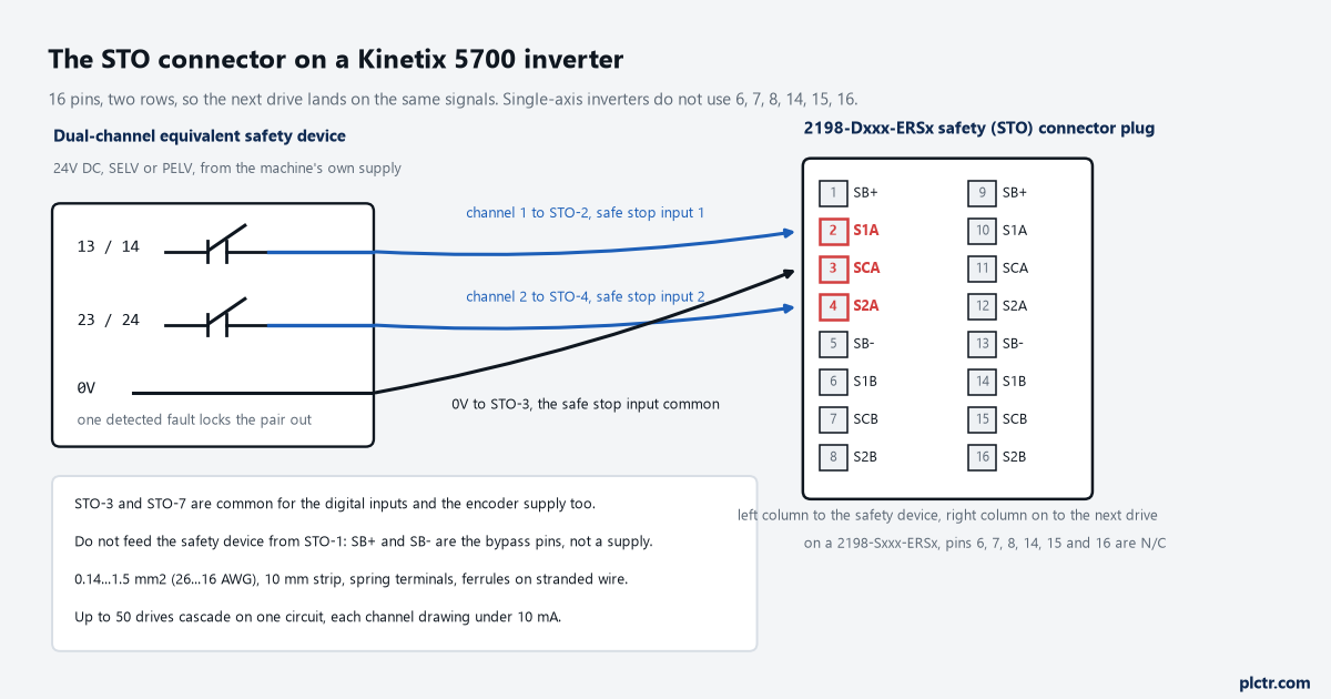
Three connections carry the whole function. The right-hand column of pins exists so the next drive can be wired from the same terminals.
Sixteen pins, and the three that carry the circuit
The plug has two rows of eight, and on a dual-axis inverter the second set belongs to axis B.
STO-1 is SB+ and STO-5 is SB-, the two bypass pins. STO-2 is S1A, safe stop input channel 1 for axis A; STO-4 is S2A, channel 2; STO-3 is SCA, the safe stop input common. On a dual-axis drive, STO-6, STO-7 and STO-8 repeat that pattern as S1B, SCB and S2B for axis B, and on a single-axis inverter those three, along with STO-14, STO-15 and STO-16, are not used at all. The wire is 0.14 to 1.5 mm², which is 26 to 16 AWG, stripped 10 mm, into a spring terminal you release by depressing the numbered tab beside the pin; stranded conductors get ferrules, which the manual pins to table D7 of ISO 13849 rather than leaving as an opinion. The external 24 V has to be SELV or PELV rated, and both channels want a proper dual-channel source — a safety relay’s two outputs, a Guard I/O module, a safety controller — not two auxiliary contacts off a starter.
One detail catches people who are wiring the drive for the first time and reading the pinout in isolation.
STO-3 and STO-7 are not private to the safety circuit. They are the common for the digital inputs and for the optional encoder supply as well, which means the 0 V you land there is the drive’s 0 V, not a floating reference belonging to the guard loop. And the manual is explicit about the other direction: do not use STO-1 as the power supply for the external safety device. SB+ is there to defeat the function, not to feed it. The 24 V for the switch, the relay, or whatever drives the two channels comes from the panel supply.
The jumpers that ship in the plug
A Kinetix 5700 inverter will not run with the safety connector empty.
Out of the box the drive is in Hardwired STO mode with no safety wiring, so for a machine that does not use the function, jumpers go in: SB+ to both safety inputs, SB- to the safety common. With those fitted the safe torque off feature is simply not in the circuit, and the drive enables the way any non-safety drive does. That arrangement is a commissioning tool. It is also the state a drive can quietly stay in for years, because nothing on the display announces that the safety function has been jumpered out, and the only way to tell from the controller is the safety supervisor state: 51 means hardwired mode with torque permitted, 8 means hardwired mode with torque disabled, and neither of them tells you whether the 24 V arrived from a guard switch or from a piece of wire between pins 1 and 2.
Count the jumpers during the FAT. Then count them again after the machine has been through its first breakdown.
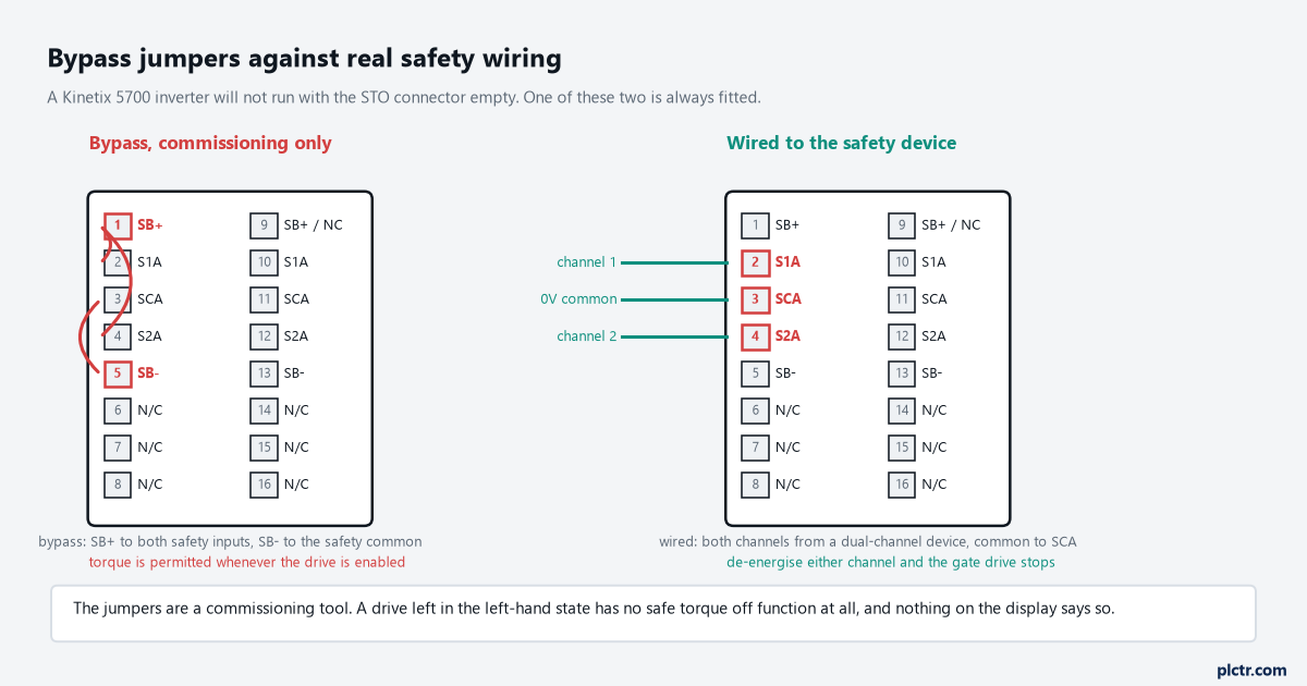
Left-hand plug: the drive runs, and there is no safe torque off function at all. This is the arrangement to look for before you trust a panel somebody else built.
When one channel opens and the other does not
This is where a correctly wired drive goes to a fault that looks like a hardware failure.
The drive watches the two channels against each other. Torque is removed as soon as the first input drops, and GuardStopRequestStatus sets at that point regardless of what the second channel is doing — the safety function has already happened. What the second channel decides is whether a fault gets posted. If both inputs are not off simultaneously within 100 ms, the request bit does not simply clear again on the way back; and if the second input has still not gone off after one second, the drive posts GuardStopInputFault. The fault is asserted even if the first input turns back on without the second ever transitioning, which is the case that catches a sticking contact or a switch actuator that is barely making. Clearing it has two conditions in series: both inputs off for more than one second, then an MAFR instruction issued from the Logix Designer application. A pulse shorter than the 700 µs rejection width is ignored outright, so the noise on a long run is not what is tripping you.
Nine times out of ten the culprit is mechanical, not electrical: a door that twists as it closes so one tongue leaves its actuator early.
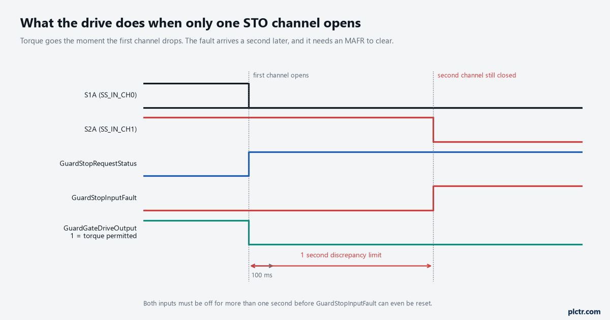
The torque is gone at the first edge. The fault a second later is a diagnostic about the wiring, not about the stop.
If you are choosing a discrepancy setting on the device side of the same circuit, the discrepancy time on a dual-channel safety input is a separate number with its own rules, and the drive’s one second window is not adjustable to match it.
What safe torque off does not do
Read this section before the commissioning test, because most of the trouble around STO is a correct function being asked to do a job nobody certified it for.
It is not an isolation method. The manual’s own attention notice says the feature is suitable only for performing mechanical work on the drive system or affected area of the machine, and that it does not provide electrical safety; the shock hazard notice on the same page says hazardous voltages can still be present at the drive in safe torque off mode, and that power must be disconnected and the voltage verified as zero before any work on the drive. Nothing about the STO connector changes the state of the AC input, the DC bus, or the motor cable. It is not a brake either. Removing torque lets a load coast, and where an external influence such as a suspended axis is present, holding it is a separate job for a mechanical brake selected and validated for that purpose. And it is not absolutely instantaneous in the way a dropped contactor is: permanent magnet motors can, if two faults arrive in the IGBT circuit at the same time, turn through as much as 180 electrical degrees before torque production ceases. On a machine somebody believes is incapable of moving, that is still movement.
It is also not a start and stop control, for the same reason no safety function is: the data behind it assumes demands, not duty cycles.
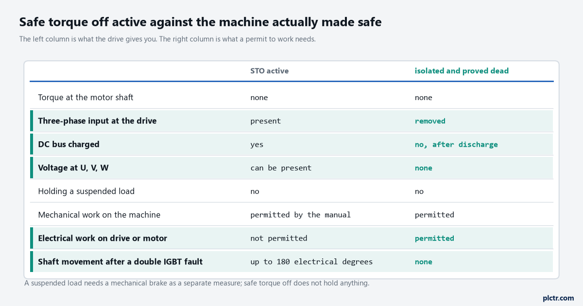
The left column is what the drive gives you. The right column is what a permit to work needs, and nothing in the left column produces it.
The PowerFlex 755 safe torque off article covers the same distinction on a drive where the function is an option module rather than built in, and the reasoning is identical because the mechanism is.
Cascading, and where the limit actually sits
The second row of pins exists so one safety device can serve a line of drives.
Wire the device to the first drive’s left-hand column, then run drive to drive from the right-hand column to the next plug’s left, and the whole group drops together. The ceiling is current, not configuration: each safety input draws under 10 mA per channel per drive, and the manual puts the maximum number of drives on one cascaded circuit at 50. On a dual-axis inverter you can feed axis A and axis B from two different safety devices, which is how two zones share a cabinet, or from one device for both axes where they belong to the same guarded space. The inputs are optically isolated and reverse-voltage protected, they read on between 18 and 26.4 V and off below 5 V, and the whole assembly only keeps its rating inside an enclosure of IP54 or better.
Fifty drives on one circuit is a wiring limit. Whether fifty drives belong in one safety zone is a question for the risk assessment, and it usually answers no.
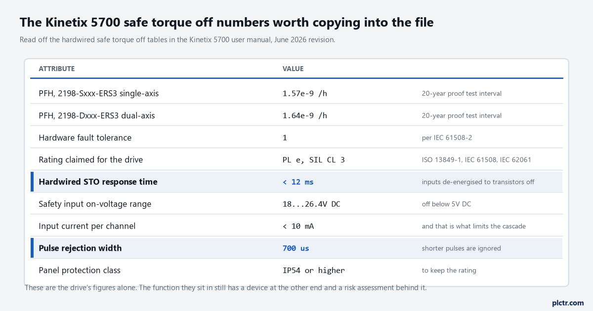
PFH values are per drive, for a 20-year proof test interval, with the demand rate assumption printed next to them. They are one subsystem of a function that still has a device at the other end.
Before any of it counts as a safety function
The drive is one subsystem, and the manual names who owns the rest of it.
Validating the sensors and actuators connected to the system, completing the machine-level risk assessment, certifying the machine to the performance level or SIL the assessment calls for, and proof testing under ISO 13849 are all listed as the system user’s responsibility. Nothing on this page replaces any of that, and a safe torque off fault is only detected on demand of the function, which is why the manual insists the function is executed again after any troubleshooting or maintenance that could have touched it. For the circuit that feeds the drive, wiring a guard switch to a 440R safety relay covers the device end, and cross-fault detection between two safety channels covers what a short between the two wires looks like before it ever reaches STO-2.
Next step: with the machine safe and the guard open, drop one channel at a time and watch GuardStopRequestStatus and the Start Inhibit bits. If either channel alone removes torque, and holding one open for more than a second posts GuardStopInputFault that only MAFR clears, the plug is wired the way its manual expects — and that test, written down and dated, is the first page of the proof test record rather than the end of the commissioning.