The 440R safety relay on the new guard, a 440R-S12R2, was showing PWR/Fault flashing red four times, IN steady red with the door shut, and the electrician had already swapped it for the spare, which did the same thing within a second of power-up. The guard switch is a single-contact tongue switch, and the link that turns one N.C. contact into two channels had been fitted between S11 and S21 – the two pulse-test outputs – instead of between S12 and S22, the two inputs. To the relay that is a short between its two test outputs, which is the cross fault the four flashes mean. Moved the link, cycled power, IN went green, OUT started flashing, and then nobody could reset it, because the reset button was being tapped and a monitored reset on this relay wants a press held between 250 ms and 3 s and acts on the release. Everything below is the SI relay from the Guardmaster GSR family wired to a tongue switch with two N.C. contacts, two 100S contactors monitored in the reset loop, and the manual’s own numbers for every terminal, with the one-contact link and the MSR127 layout covered where they differ.
Two links, two different jobs. One turns a single contact into two channels, the other turns a monitored reset into an automatic one.
What each terminal on the 440R safety relay is for
Fourteen terminals, and the manual’s table of them is the drawing you want taped inside the door.
Across the top of the 440R-S12R2 the face reads S11, S21, A1, S34, 13, 23; across the bottom S12, S22, Y32, L11, A2, 14, 24. A1 and A2 are the 24 V DC supply, PELV or SELV, and A2 has to be the common of that supply because every input on the relay is referenced to it. S11 and S21 are not inputs. They are the pulse-test outputs for channel 1 and channel 2, each one carrying 24 V with short dips on it – 1.5 and 3 ms wide, repeating every 13.6 ms on the SI – and the relay watches for its own dips coming back on S12 and S22 to prove the wire is the wire it thinks it is. S12 is the safety input for channel 1, S22 for channel 2, so a guard switch with two N.C. contacts is wired one contact from S11 to S12 and the other from S21 to S22. S34 is the reset and monitor input, and it is where the reset button and the contactor feedback contacts go. 13/14 and 23/24 are the two N.O. safety outputs, and the manual is specific about what is behind them: two positive-guided relays inside the housing, in series, so that one welded internal contact does not keep an output closed. Y32 is the auxiliary output, a transistor that is on when the safety outputs are off – a standard signal for the PLC, never a safety one. L11 is the single wire safety output, for expanding the function into a DI or EM relay, and it stays empty on a one-relay machine. The input side has numbers worth having: the on voltage is 11 V minimum, the on current 11 mA at 24 V, off is anything below 5 V, and the manual allows 900 Ω of loop resistance on the SI before the input stops reading closed, which is a long cable run before the switch itself starts to matter.
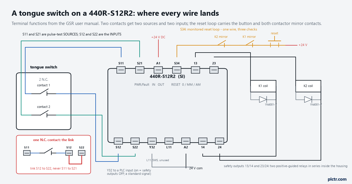
S11 and S21 are sources, S12 and S22 are inputs. The inset is the single-contact case: one contact from S11 into both inputs, with the link on the input side.
The safety outputs need suppression on the coils, and the manual makes it a requirement rather than a suggestion. For a 24 V DC coil a diode from 1N4001 to 1N4007 across the coil, as close to it as the terminals allow; for AC coils a varistor. The contacts are rated AC-15 at 1.5 A and 250 V AC and DC-13 at 2 A and 24 V DC, with a 6 A slow-blow fuse in front of them, and a 100S-C09 coil sits well inside that. Ten million mechanical operations is the life figure, and an unsuppressed coil is how you fail to reach it.
Diodes on the coils are wiring, not an option.
The link, and which side of the contact it goes on
A switch with one N.C. contact still gives the relay two channels, and the manual’s Figure 9 is the whole of the method: one side of the contact to S11, the other side to both S12 and S22. The link is between the two inputs. What it costs is the cross-fault cover between the two wires that a two-contact switch gets for free, because both inputs are now fed from one test source, and a short from that one wire to 24 V is still seen while a short between two wires that carry the same signal is not. The link that went wrong on the machine above was between S11 and S21, and to the relay that is the exact condition its Table 12 lists under four flashes: a short circuit from S11 to S21. Not a damaged relay, and the spare was never going to behave differently.
The link goes across the inputs, S12 to S22. Never across the sources.
The second link is the one that decides what kind of reset you have. With the rotary switch at AM, automatic/manual, the outputs turn on as soon as the inputs are closed provided S34 has 24 V on it, and the manual shows three ways to get 24 V there: a straight wire, a wire through the contactors’ N.C. monitoring contacts, or an N.O. push button – and with a button in automatic mode the reset happens when the button is pressed, on the leading edge, not when it is released. A straight link from 24 V to S34 with the switch at AM is an automatic reset with no contactor monitoring at all. It is a legitimate configuration for a guard that only allows partial body access with a start elsewhere in the control system, and it is not the configuration for a walk-in guard, which is the reason the switch on the front has a second position.
The monitored reset: what the relay checks before it closes
With the switch at MM the relay will not close its outputs on the guard shutting, and it will not close them on the button going down either.
The reset signal on S34 has to go from 0 V to 24 V and back to 0 V, and the whole excursion has to last between 250 and 3000 ms; the reset occurs on the trailing edge, when the button is released. A tap of 100 ms is ignored, and the manual says so in as many words – too short or too long and the reset is not executed, try again – and a button held for four seconds, or tied down, or shorted, produces no trailing edge inside the window and no reset. That is what the word monitored buys. Rockwell’s Safebook 5 puts the requirement in one sentence: the relay will not allow a restart until there is a change of state at the reset button after the guard has closed, so that the reset proves the contactors are off, the interlock circuits are closed, and the actuator has not been bypassed or blocked. The same document notes that the standard cites the falling edge for this, and this relay acts on the falling edge. The inputs matter too. The safety inputs have to be closed before the reset, and the manual’s off-pulse table says what closed means: an input that opened for 25 ms or more is seen opening and closing again; one that opened for between 7 and 25 ms turns the outputs off but is not seen coming back, and the guard has to be cycled properly; under 7 ms the relay does not see it at all. A guard switch that bounces when the door slams sits in that middle band on a bad day, and the operator then presses a perfectly good reset against an input the relay considers still open.
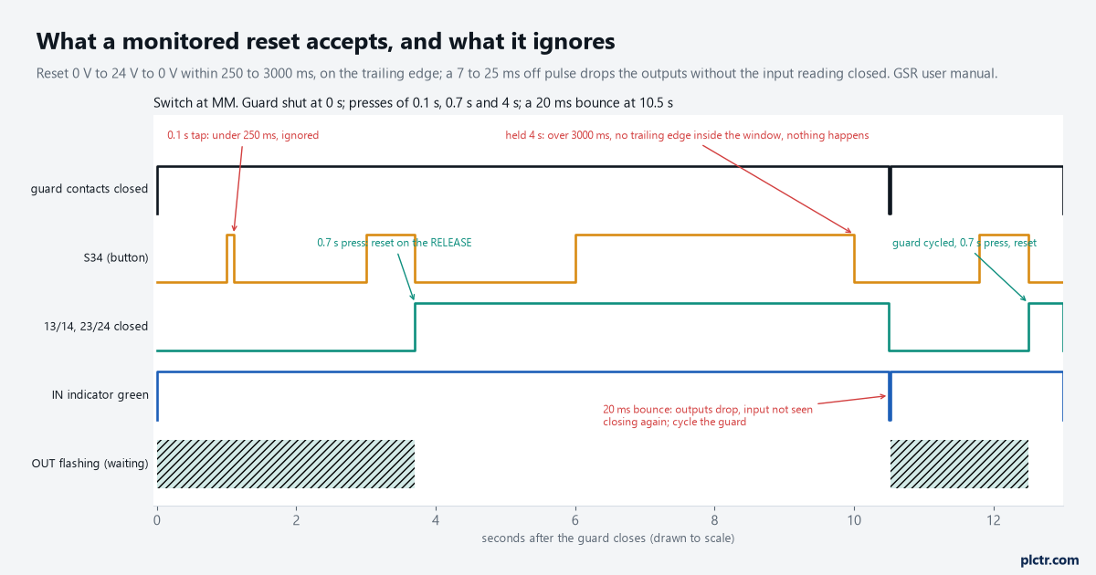
The relay acts on the release, and only if the press lasted 250 to 3000 ms. Everything outside the window is the button doing nothing, which is the point of it.
The contactor feedback goes in the same loop. K1 and K2 each have a mirror contact, N.C., and both go in series with the button between 24 V and S34, so a contactor that has welded and not dropped out holds the loop open and the press never reaches the relay – the Safebook’s description of the fault being revealed on the next cycle. Which contact that has to be, and why a snap-on auxiliary block is not it, is the whole of the mirror contact article. Where the reset comes from a PLC output rather than a button, the manual asks for a pulse of 260 to 2990 ms rather than the full window, for margin.
Button and both mirror contacts in one series loop into S34. One wire, three checks.
Setting the switch, and the five-minute rule
The reset mode is a rotary switch on the front with three positions, 0, MM and AM, and it is not set by turning it to MM.
Power off, switch to 0. Power on, and after a moment PWR/Fault flashes red at 1 Hz, half a second on and half off, which is the relay telling you its stored configuration has just been erased. Turn the switch to MM. The IN indicator now flashes the switch setting back at you – count after the first pause, the manual says the first cycle can be wrong – and then power has to be cycled to store it. The relay compares the switch to the EEPROM on every power-up, so a switch nudged later shows as green with two red flashes and the relay keeps running on the stored setting. And the rule that catches people: complete the configuration by cycling power within five minutes of turning the switch, or the relay faults permanently. The wiring has to be finished and the guard closed during configuration, because the relay sends its test pulses out during the process to learn how it is wired.
Switch to 0, power on, set MM, cycle power. Inside five minutes, with the guard shut.
What the indicators say when it will not reset
Three indicators, and reading them in order is faster than swapping anything.
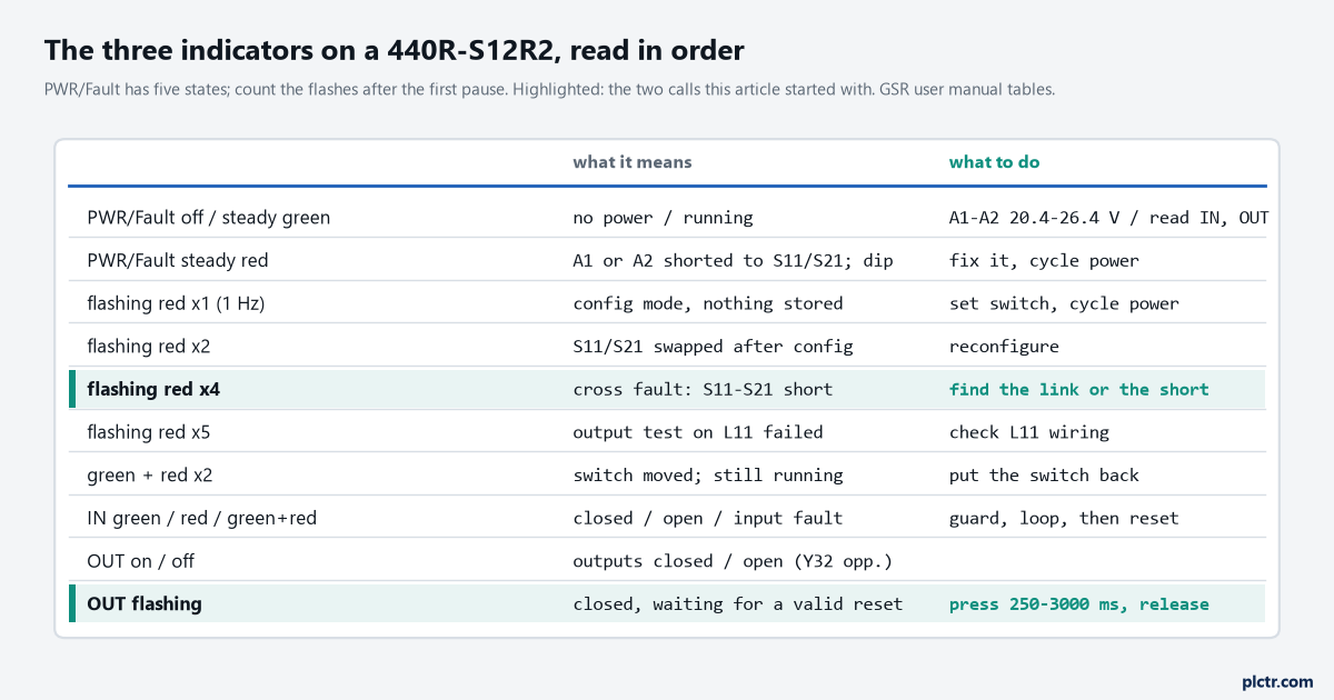
Four flashes with a link across S11 and S21 is the call that started this article. OUT flashing is not a fault: it is the relay waiting for a reset it will accept.
PWR/Fault has five states. Off is no power, and the first measurement is A1 to A2, which should read 20.4 to 26.4 V. Steady green is running. Steady red is a nonrecoverable fault the tables do not list separately – a short from A1 or A2 to S11 or S21, a power dip, noise – and clears with a power cycle. Flashing red is counted: one flash at 1 Hz means configuration mode with nothing stored, two means the stored configuration is invalid, which includes S11 and S21 swapped after configuration, four is the cross fault – S11 shorted to S21, or too much capacitance on the input wiring distorting the pulses – and five is a failed output test on L11, which on a relay with nothing wired to L11 points at a short on that terminal. Green with a flashing red is the switch disagreeing with the EEPROM after somebody touched it. IN is steady green with both S12 and S22 circuits closed, steady red with them open, and green with flashing red for a recoverable input fault, which clears with a reset once the cause is gone. OUT on means 13/14 and 23/24 are closed and Y32 is off; OUT flashing means the inputs are closed and the relay is waiting for a reset, which is the state that produces the most calls and is not a fault at all.
The thing everyone checks first
The relay, by swapping it.
A GSR relay that faults on power-up with the same flash count as the one it replaced has told you the fault is in the wiring, and the manual gives you the meter readings to find it. With the guard open, S11 reads about 14 V on a DC multimeter and S21 about 18 V – different because the two pulse patterns are different, S11 being off for longer – and with the guard closed S12 and S22 read very close to those. A reading at S12 well below S11 with the contact closed is loop resistance or capacitance, and the limits are 900 Ω, 160 nF between S11 and S21, and 320 nF from either to ground. A cable run past those numbers does not fault the relay outright; it deforms the leading edge of the pulses until, one damp morning, it does. Only after those readings is it worth putting a scope on S11 and S21 to look at the pulse shape, and the manual says what you are looking for – clean and square.
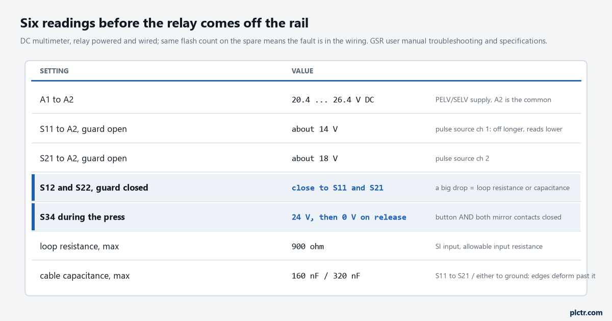
Six readings, all with the relay in place. The relay comes off the rail last, and only if all six are right.
Meter first. The spare relay is the last thing to try, not the first.
If the panel has an MSR127 in it
The older Minotaur MSR127RP is the relay most of these guards were wired to originally, and 440R-TD001A still lists it: one N.C., two N.C. or OSSD inputs, three N.O. safety outputs and one N.C. auxiliary, a 15 ms response time, and cross-fault monitoring when it is wired as two N.C. inputs. The RP suffix is the monitored manual reset and TP is automatic/manual, on that relay a different part number rather than a switch, and the datasheet says the TP’s reset can be jumpered. The current drop-in for it is the CI relay, 440R-S13R2, which the GSR manual describes as having the same number of inputs and outputs, the same width and the same terminal locations as the MSR127, with the reset mode on a switch. On the SI relay you get two safety outputs instead of three and a 35 ms response time rather than 15, which is the difference between the two that belongs in the safety distance arithmetic. Whether a relay is the right box for this machine at all is a separate question, and the answer for one guard and one contactor pair is usually yes.
Next step
Put the manual’s terminal table on the drawing next to the relay, with the two links named for what they are – S12 to S22 for a one-contact switch, 24 V to S34 only when the switch is at AM and the risk assessment allows it. Then time the reset button with a stopwatch across ten presses by the people who will use it; a press under 250 ms is common on a button mounted at chest height, and the fix is training or a different button, not a longer window. The same reset discipline moves across to a safety controller unchanged, which is the rising-edge reset article, and what the relay’s pulse test is doing between S11 and S12 is what the controller’s test outputs do, worked through in cross-fault detection between two channels. When the machine grows a second guard and an E-stop, the same function on a controller is the next article in this set.
Link across the inputs, feedback in the reset loop, switch set with the guard shut. Then the meter, before the spare.