At 900 m/min a draw of 0.20 percent between two sections comes to 1.8 m/min. That is the resolution the speed reference has to carry, so a 16-bit reference scaled 0 to 1000 m/min will do it and a percentage in whole numbers will not. PLC pulp and paper work is mostly about that relationship: speed references that hold a draw of a fraction of a percent, stock loops that are slow and full of dead time, and a winder that has to build a roll nobody complains about. Break any of them and the sheet tells you immediately. The machine in this walkthrough is a 3.6 m fine paper machine running 900 m/min with seven driven sections.
Map the machine into sections and pick the reference chain
| Section | Drive | Typical draw from previous | Notes |
|---|---|---|---|
| Wire, couch | PowerFlex 755 400 kW | Master, 0 percent | Sets machine speed, everything follows |
| Press 1 | PowerFlex 755 250 kW | 0.15 to 0.25 percent | Sheet is wet and weak, keep it small |
| Press 2 | PowerFlex 755 250 kW | 0.10 to 0.20 percent | |
| Dryer group 1 | SINAMICS S120 180 kW | 0.30 to 0.50 percent | Shrinkage starts here |
| Dryer group 2 | SINAMICS S120 180 kW | minus 0.20 to minus 0.40 percent | Negative draw, sheet shrinks |
| Calender | PowerFlex 755 160 kW | 0.10 percent | |
| Reel | PowerFlex 755 200 kW | 0.20 percent | Torque follows on the drum |
Draw is the speed difference between two sections expressed against the upstream speed. At 900 m/min a draw of 0.20 percent is 1.8 m/min. That is the resolution your speed reference has to carry, so a 16-bit reference scaled 0 to 1000 m/min at 0.015 m/min per bit is adequate and a percentage reference scaled in whole numbers is not.
Send the references as a scaled DINT in a cyclic connection rather than through messaging. On EtherNet/IP a PowerFlex 755 with a 20-750-ENETR takes a 32-bit reference in the drive datalinks at an RPI of 8 ms. On PROFINET the SINAMICS S120 takes the reference in standard telegram 3, isochronous, with a 4 ms send clock on this machine. Both are fast enough. Explicit messaging at 250 ms is not, and it shows up as a slow surge in the draw whenever the machine changes speed. Drive integration detail is in PLC motor control and drive systems and the network side in EtherNet/IP PLC communication.
Calculate the draw and ramp the sections together
(* MachineDrives, 10 ms periodic task, ControlLogix 1756-L85E *)
(* master ramp, then every section derives its own reference *)
(* Logix ST has no LIMIT function, so the clamps are written out *)

Master_Target := Operator_Speed_SP;                   (* m/min *)
IF NOT Machine_Run THEN
    Master_Target := 0.0;
END_IF;

Step := Master_Target - Master_Ref;                    (* Accel_Step = 0.05 m/min per 10 ms *)
IF Step > Accel_Step THEN
    Step := Accel_Step;
ELSIF Step < -Decel_Step THEN
    Step := -Decel_Step;
END_IF;
Master_Ref := Master_Ref + Step;
IF Master_Ref < 0.0 THEN Master_Ref := 0.0; END_IF;
IF Master_Ref > 1000.0 THEN Master_Ref := 1000.0; END_IF;

FOR i := 1 TO 7 DO
    (* draw is held against the section in front, not against the master *)
    IF i = 1 THEN
        Sec[i].Ref := Master_Ref;
    ELSE
        Sec[i].Ref := Sec[i-1].Ref * (1.0 + Sec[i].Draw_Pct / 100.0);
    END_IF;

    (* tension trim only after the whole line is up to reference, clamped to 0.2 percent *)
    IF Line_AtRef AND Sec[i].Trim_Enable THEN
        Trim := Sec[i].Trim;
        IF Trim > 0.002 THEN Trim := 0.002; END_IF;
        IF Trim < -0.002 THEN Trim := -0.002; END_IF;
        Sec[i].Ref := Sec[i].Ref * (1.0 + Trim);
    END_IF;

    (* 0 to 1000 m/min into a 16-bit range; Logix rounds the REAL on assignment *)
    Sec[i].Cmd := Sec[i].Ref * 65.535;
END_FOR;

Line_AtRef := 1;
FOR i := 1 TO 7 DO
    IF ABS(Sec[i].Fbk - Sec[i].Ref) > (Sec[i].Ref * 0.001) THEN
        Line_AtRef := 0;
    END_IF;
END_FOR;
Three things in that snippet matter on a running machine. The draw chains section by section, so a change at press 1 moves everything downstream and the sheet stays intact. The trim is clamped to plus or minus 0.2 percent, which is enough to correct a load imbalance and too small to tear the sheet if a tension transmitter fails. And Line_AtRef uses a proportional window, 0.1 percent of reference, not a fixed number, because 1 m/min of error means something different at 200 m/min than at 900. Writing the clamps as IF blocks is not a style choice: Logix ST has no LIMIT or MIN function, and the alternative is an HLL instruction with a backing tag per clamp.
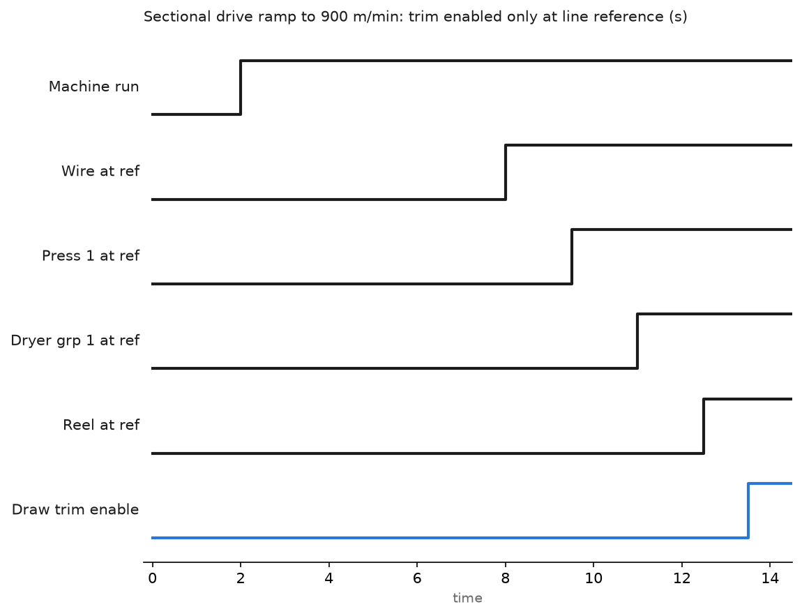
The time axis on that chart is compressed to show the order of events. At 0.05 m/min per 10 ms scan the real ramp to 900 m/min takes three minutes, and the sections reach their at-reference window a few seconds apart because each drive settles against its own load.
The trim enable at the end of the ramp is the part people leave out. Enable tension trim while the sections are still accelerating and the trim integrator fights the ramp, which puts a slow oscillation into the draw and breaks the sheet at the next splice.
Control consistency first, basis weight second
The stock side is slow and it has transport delay in it. Fighting that with a fast loop is how you get a machine that hunts all shift.
- Thick stock leaves the machine chest around 3.5 percent consistency. A blade type transmitter measures it and a valve on the dilution water holds the setpoint. This loop is local and reasonably quick, integral around 40 seconds.
- Headbox consistency lands near 0.8 percent after dilution. Measure it, do not assume it from the thick stock reading.
- Basis weight comes from the scanner at the reel, which sees the sheet 25 to 40 seconds after the headbox made it. Never close a fast loop around that.
- Run the basis weight as a ratio instead. Stock flow setpoint equals target basis weight times machine speed times trim. The ratio does most of the work with no feedback delay at all.
- Let the scanner trim the ratio slowly. One correction per scan, gain under 0.3, and no correction at all while the scanner is in a reversal or the sheet is off.
- Handle moisture separately with dryer steam pressure and the steam box, cascaded so the moisture controller sets a differential pressure setpoint across the dryer group.
A Smith predictor helps on the basis weight trim if the dead time is stable. On a machine that changes speed through the day the dead time changes with it, so scale the predictor delay from machine speed rather than leaving it fixed. The loop mechanics themselves are ordinary, and the tuning approach is in implementing PID control in PLC systems.
Set winder tension with a taper, not a constant
A finished roll is not wound at one tension. Wind the outside as hard as the core and the roll dishes or bursts.
- Start at 0.40 kN per metre of width for 80 g/m2 fine paper, measured by a load cell roll rather than estimated.
- Taper down to 60 percent of that value by full diameter. On a 1200 mm roll that is a linear taper against diameter, set in the HMI as a start value and an end percentage.
- Calculate diameter from the ratio of drum speed to core speed and filter it, or take it from an ultrasonic sensor. The calculated value is smoother, the sensor is right after a splice.
- Torque reference equals tension times radius divided by gear ratio, plus inertia compensation. During acceleration the inertia term is the bigger of the two on a big roll, so include the roll inertia as it builds instead of using a fixed figure.
- Watch out at the change from core drive to surface drive. The handover needs a ramp of a second or so with both drives sharing, otherwise the tension spikes and the web breaks at the worst place, right at the start of a new roll.
Field notes
The coupling that slipped 0.3 percent. Dryer group 2 started flapping the sheet after a maintenance shut. The drive reported correct speed, the draw looked right on the HMI, and the sheet said otherwise. The encoder coupling on the 1024 ppr feedback had backed off and was slipping under load. We caught it by timing a mark on the felt against the reported speed with a stopwatch, an old trick that still works. Anything driving a draw needs a feedback check against surface speed at commissioning, written down in the file.
Trim enabled too early. After a control upgrade the tension trim came on with the run command instead of at reference. Every startup produced a 1 Hz surge in the press section and roughly one break in three. The Line_AtRef gate above fixed it, and the same logic now blocks trim during any speed change greater than 2 percent.
PROFINET update jitter. A dryer section drifted in draw by about 0.1 percent at irregular intervals. The PROFINET connection was RT rather than IRT, and the send clock was competing with an engineering laptop plugged into a machine switch. Moving the drives to isochronous IRT and locking the switch ports removed it completely. Do not leave a spare port live on a drive network.
Flat consistency reading. A blade transmitter on thick stock stopped moving over a weekend because the sample line was plugged with fibre. The reading sat at 3.48 percent while the real consistency wandered, so the dilution valve drove itself to a limit and basis weight went with it. A rate of change alarm, no movement greater than 0.02 percent in 30 minutes while the pump runs, now flags it within the hour.
Frequently asked questions
Should draw be set in percent or in speed difference?
Percent. Draw scales with machine speed, so a percentage stays correct through the speed range while a fixed m/min difference gets far too aggressive at low speed during threading.
PLC or a dedicated drive controller for the sections?
Both work. A ControlLogix with a 10 ms periodic task and cyclic drive connections is plenty for seven sections on a 900 m/min machine. Above that, or with load sharing pairs on one shaft, a dedicated drive controller with a faster reference update earns its money.
How do I find which section caused a break?
Log speed feedback, torque and load cell tension for all sections into a 50 ms buffer and keep the last 10 seconds before the break trigger. Without that buffer everyone guesses, and the guess is usually wrong.
What causes draw to drift slowly over a shift?
Roll diameter changes as the covers wear, felts stretch, and the sheet shrinks differently as moisture moves. Drifting draw is normal. Drifting draw with a step change in it is a mechanical or feedback fault.
Is a dancer better than a load cell?
On a winder a load cell is the more direct measurement and gives a faster loop. Dancers still earn their place where the web has to pass through an accumulator or the tension varies a lot at splices.
Next step
The feedback device is the weak point in every one of these loops, so it is worth being fussy about mounting and resolution. What is an encoder, usage areas and types covers the selection, and PLC motion control goes further into geared and cammed relationships when a section has to follow a position rather than a speed. The same draw arithmetic on a different machine, with a stop that has to leave the broken end findable, is in textile warper and stenter control.