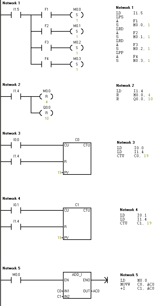
PLC Programming Calculator Example
PLC Programming Example
Design the circuit that adds up to 2 sensors (input), presses the F1 button, subtracts when the F2 button is pressed, divides when the F3 button is pressed, multiplies when the F4 button is pressed, and gives the output to the output.
Let’s do the PLC simulation.
| I1.5 | Start |
| I0.0 | 1st Sensor |
| I0.1 | 2nd sensor |
| I1.4 | Reset |
| F1 | Addition |
| F2 | Subtraction |
| F3 | Division |
| F4 | Multiplication |
| Q0.0 | The output is 1 when the output is active. |
| Q0.1 | The output is 2 when the output is active. |
| Q0.2 | The output is 3 when the output is active. |
| Q0.3 | The output is 4 when the output is active. |
| Q0.4 | The output is 5 when the output is active. |
| Q0.5 | The output is 6 when the output is active. |
| Q0.6 | The output is 7 when the output is active. |
| Q0.7 | The output is 8 when the output is active. |
| Q1.0 | The output is 9 when the output is active. |
| Q1.1 | The output is 10 when the output is active. |
| Q1.1-Q0.0 | The output is 11 when the output is active. |
| Q1.1-Q0.1 | The output is 12 when the output is active. |
| Q1.1-Q0.2 | The output is 13 when the output is active. |
| Q1.1-Q0.3 | The output is 14 when the output is active. |
| Q1.1-Q0.4 | The output is 15 when the output is active. |
| Q1.1-Q0.5 | The output is 16 when the output is active. |
| Q1.1-Q0.6 | The output is 17 when the output is active. |
| Q1.1-Q0.7 | The output is 18 when the output is active. |
| Q1.1-Q1.0 | The output is 19 when the output is active. |


