Write 80 into a SunSpec inverter’s WMaxLimPct register and the plant can curtail to 8 percent, because model 123 reports a scale factor of minus 1 and the value is read in tenths. A 12 MW array making 1 MW on a clear afternoon is what that looks like from the revenue meter. The rest of the job has the same shape: the inverter, the turbine, the battery BMS and the grid operator each hold their own idea of the number, and your controller has to make them behave as one plant and fail into a safe state when a link drops. The examples below come from a 12 MW solar site with trackers and a 6 MWh battery, plus notes from a small wind site.
Talk to the inverters over SunSpec Modbus, properly
SunSpec is a register layout over Modbus, TCP on most utility inverters and RTU on some, and the parts you use every day are small.
| Model | What it holds | Registers used here |
|---|---|---|
| Common, model 1 | Manufacturer, model, serial, firmware | Found by the SunS marker at 40001 |
| Inverter, model 103 | AC power, current, voltage, frequency, temperature, status | W, Hz, DCW, St, Evt1 |
| Immediate controls, model 123 | Power limit, power factor, connect and disconnect | WMaxLimPct, WMaxLim_Ena, WMaxLimPct_RvrtTms |
Three habits that save a week of commissioning:
- Discover the block addresses at startup instead of hard coding them. Read 40001, confirm the
SunSidentifier, then walk the model headers. Firmware updates move blocks, and a hard coded offset turns into a power limit written into a temperature register. - Apply the scale factor every time. A power value comes back with its own
sunssfexponent. A limit of 80.0 percent is written as 800 with a scale factor of minus 1. Ignore it and you write 80 tenths of a percent. - Set
WMaxLimPct_RvrtTmsdeliberately. That revert timeout tells the inverter how long to hold your limit before returning to full output. On a curtailed site, a value of 0 means the limit sticks forever including after your PLC dies. A value of 300 seconds means the limit lifts five minutes after your last write. Pick one and refresh the limit on a timer that comfortably beats it.
The tracker controllers sit on the same network and take an angle or a mode command. Stow logic belongs in the PLC, not in a spreadsheet of intentions. Wind stow at a 10 minute average above 20 m/s, an immediate stow on any 3 second gust above 25 m/s, and a snow stow at a steep angle when panel temperature and precipitation both say so. Track the return to normal with a hysteresis of at least 4 m/s and a 15 minute hold, otherwise the rows oscillate between stow and track all afternoon.
Keep the wind turbine pitch loop inside its rate limits
Small wind sites and retrofits run on a Bachmann M1 or a Beckhoff CX series controller under TwinCAT, with the safety chain in hardware.
- Below rated wind the pitch stays near fine, about 0 to 2 degrees, and the converter controls torque to track the optimum tip speed ratio.
- Above rated wind a collective pitch PI loop holds generator speed by pitching towards feather. Gain scheduling against pitch angle matters, because the blade is far more effective at 15 degrees than at 2.
- Limit the pitch rate to around 8 degrees per second in normal control. The emergency feather path is separate, runs at the maximum the accumulator allows, and is triggered by hardware.
- Yaw on a 10 minute average of the nacelle vane error. Above 8 degrees, yaw at 0.5 degrees per second, release the brake before commanding the drive, and reapply it after motion stops. Chasing the instantaneous vane reading wears out the yaw gears and gains nothing.
- Count cable twist. At plus or minus 3 turns force an untwist sequence, and at 4 turns trip. This is a counter that must survive a power cycle, so keep it retentive and write it to the same place as the operating hours.
The overspeed, vibration and emergency stop chain is hardwired in series with the safety valve that dumps the pitch accumulator. The PLC reads that chain and reports it. It does not form it.
Handshake with the battery BMS before closing a contactor
The battery is the one subsystem that can hurt the site without your permission. The handshake is worth writing down rung by rung.
- PLC reads pack state from the BMS: SoC, pack voltage, maximum charge current, maximum discharge current, fault word.
- PLC checks its own operating window: SoC between 15 and 90 percent, every cell temperature between 5 and 45 C, no fault bits. The BMS holds its own hard limits outside that window, and the PLC window sits inside them on purpose so the BMS never has to act first.
- PLC requests the contactor close. The BMS runs the precharge, then closes the main contactor and reports closed within 2 seconds.
- A heartbeat runs both ways at 500 ms. If either side misses it for 2 seconds, the BMS opens the contactor and the PCS stops.
- Power commands are clamped to what the BMS reports right now, not to the nameplate. A cold pack at 5 C might allow a fifth of the rated charge current.
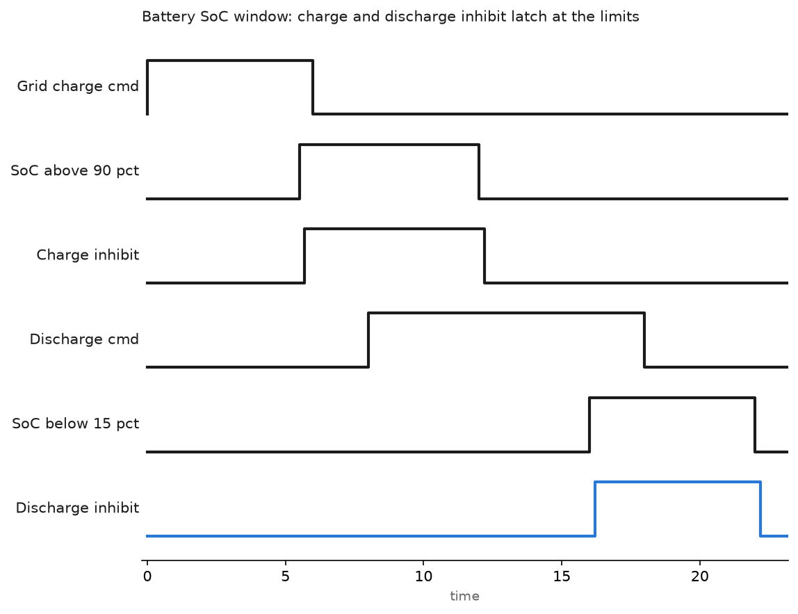
Note the small gap between the SoC threshold and the inhibit, drawn out of scale here. That is the deliberate 0.2 second filter on the SoC crossing, because a noisy SoC reading at exactly 90 percent will otherwise chatter the charge command against the contactor duty cycle. The inhibit holds until SoC is back inside the window. Taper before the limit as well: derate charge power linearly from 100 percent at 85 percent SoC down to 20 percent at 90, so the plant glides into the limit instead of hitting a wall.
Accept curtailment commands without trusting them
A grid operator setpoint arrives over DNP3 as an analog output, group 41, or over IEC 60870-5-104 as a setpoint command, and lands in the PLC as a number. Treat it as untrusted input.
Rung 22 (GridInterface, 200 ms periodic task):

  ---] [---------] [-----------] [-----------]/[--------( )---
  Curtail_Rcvd  SP_InRange   Comms_Healthy   Local_Ovr    Curtail_Valid

Rung 23:  only a validated setpoint reaches the inverters
  ---] [--------------[MOV Curtail_SP_Raw  Curtail_SP_Active]---
  Curtail_Valid

Rung 24:  confirm the plant actually followed within 60 s
  ---] [-----------]/[----------[TON Curtail_Fail_T Preset=60000]------------
  Curtail_Valid   Plant_At_Limit

Rung 25:
  ---] [------------------------------------( )---
  Curtail_Fail_T.DN                      Curtail_Alarm
SP_InRangechecks 0 to 100 percent of plant rating. A value outside that is rejected and the previous limit stays, with an alarm.Comms_Healthyis the DNP3 link state plus the object quality flag, not just a TCP socket that is open. A restarting master can send a valid looking zero.Plant_At_Limitcompares the sum of measured inverter power against the commanded limit with a 2 percent band, and is only meaningful when available power exceeds the limit, so gate the timer on irradiance or on the pre-curtailment output as well. Without that feedback you will never notice the day one inverter ignores the write.- Decide the comms loss behaviour with the network operator and write it into the functional design. Some codes want the last valid setpoint held, others want a default limit after a fixed time. Guessing here is how a site gets a non-compliance letter.
Ride-through is the other half of grid code compliance, and it belongs in the inverter. During a voltage dip the inverter has to stay connected along a defined voltage against time envelope. Your PLC must not issue a stop or a disconnect during that window because it saw an undervoltage on its own metering. Block plant level disconnect commands for the ride-through duration, typically a few hundred milliseconds to a few seconds, and let the inverter protection decide.
Field notes
The scale factor nobody applied. A new site curtailed to 8 percent instead of 80 because the integrator wrote 80 into WMaxLimPct while the model reported a scale factor of minus 1. The plant made 1 MW on a clear day for two days before anyone looked. Read the scale factor register at startup and apply it in the same function that does the write.
Contactors that opened every time the network reconverged. The BMS heartbeat crossed a managed switch running classic spanning tree. Every topology change took about 30 seconds to reconverge, the heartbeat missed, and the battery dropped offline. Moving the BMS and PCS to a direct link and enabling RSTP elsewhere ended it. Anything with a 2 second watchdog does not belong on a network segment that can go quiet for 30.
A zero that was not a command. The SCADA master restarted and sent an analog output of 0 with an offline quality flag. The old logic took it, the site curtailed to nothing for 20 minutes on a sunny afternoon, and the loss was easy to calculate. The quality flag check in Comms_Healthy came straight out of that day.
Stow that watched the wrong number. Tracker stow used only the 10 minute average wind speed. A short front pushed 28 m/s gusts through the site while the average sat at 14 m/s, and two rows were bent. The gust channel, a 3 second peak from the same anemometer, now forces a stow independently of the average.
Frequently asked questions
Modbus TCP or DNP3 for a renewable site?
Both, in different places. Modbus TCP inside the plant for inverters, trackers and meters. DNP3 or 60870-5-104 to the grid operator, because those protocols carry quality flags, timestamps and event buffering that Modbus does not.
Where should curtailment be divided between inverters?
Spread it proportionally to each inverter’s available power rather than by an equal percentage. A string with a shaded array cannot give its share, and equal percentage splitting leaves the plant below the allowed limit.
Does the PLC need to do maximum power point tracking?
No. MPPT belongs to the inverter and runs in the millisecond range on its DC side. The PLC sets limits and modes, and it collects performance ratio data to find the strings that underperform.
How do I test grid code functions without a grid simulator?
Test what you can at the plant boundary: setpoint handling, ramp rates, comms loss behaviour and reporting. Ride-through itself is a type test on the inverter, and the certificate comes from the manufacturer. Your acceptance test proves you do not interfere with it.
Next step
Every fault above showed up first as a data problem rather than an equipment problem, so treat the monitoring path as part of the plant. Remote monitoring and control of PLC systems covers stale data handling and alarm paths for unattended sites, PLC communication protocols for SCADA goes deeper into the protocol choices above, and implementing cybersecurity measures for PLC systems matters the day your site gets a routable link to a grid operator.