Adding an Axis to a Kinetix 5700 System: the Module, the Axis, and the Four Places to Set It
The eighth axis on the line is a 2198-D032-ERS4 in the last 55 mm of the rail, and getting it into the project is four dialogs and about twenty minutes. What takes the rest of the morning is everything those four dialogs do not mention: the module puts another 390 µF onto a DC bus that nobody has re-totalled since commissioning, and it brings a second axis channel with it whether a motor is ever wired to that half or not.
Four places, in this order. The Module Definition dialog on the new inverter, the Power page where Bus Configuration and Bus Sharing Group live, the axis itself as an AXIS_CIP_DRIVE tied to a specific channel on that module, and the motion group’s Axis Assignment tab. Miss the fourth and the axis is not faulted, it is simply ungrouped, and an ungrouped axis is unavailable for use — the manual’s own words, and there is no error to tell you.
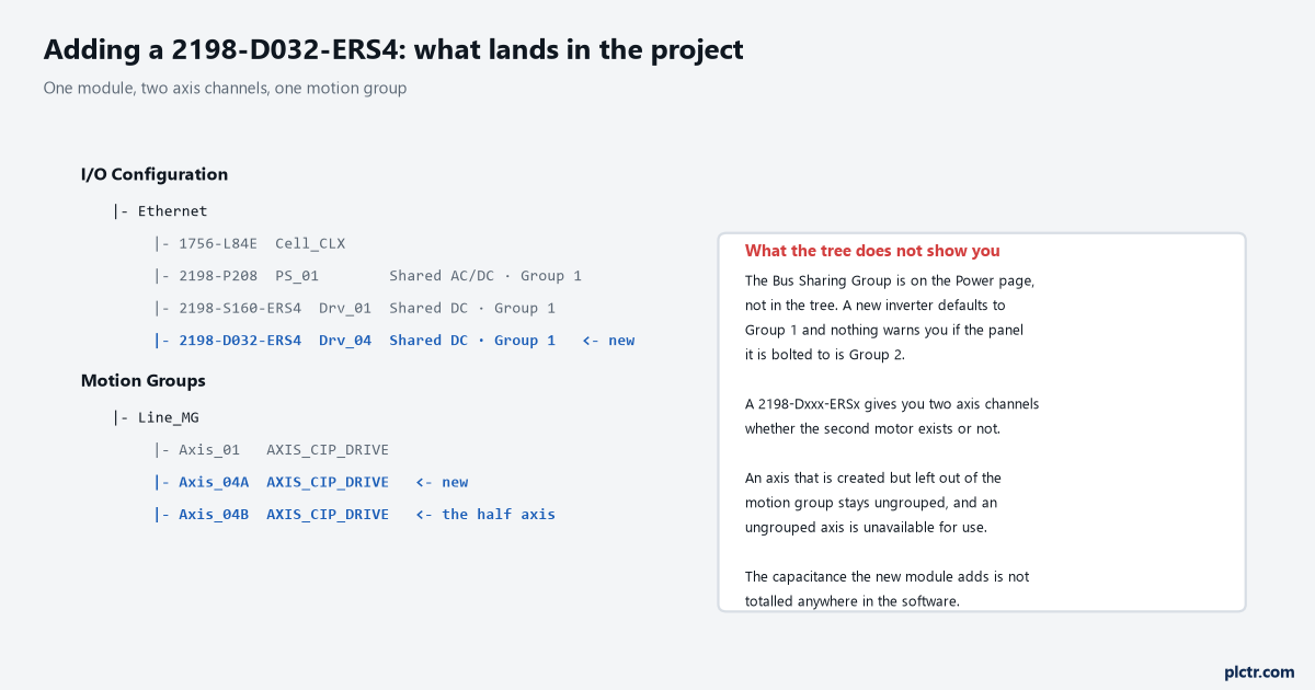
The tree shows the module and the axes. It does not show the bus group, the capacitance, or the fact that one of those two axes may have nothing connected to it.
The module first, and what Module Definition decides
Right-click the Ethernet bridge, choose New Module, filter on Motion and Allen-Bradley, type 2198 into the search box, and pick the exact catalogue number that is bolted to the panel.
Name it and give it the address, then open Module Definition, because four fields there are decisions rather than defaults. Revision has to be one the drive’s firmware can satisfy. Electronic Keying is Exact Match or Compatible Keying and it is never Disable Keying — the configuration and startup manual says that outright for motion and safety applications, and it is the one keying choice that turns a wrong module into a silently working one. Connection is Motion Only, Motion and Safety, or Safety Only: Motion Only covers hardwired STO mode and also the case where a second controller owns the integrated safety connection, while Safety Only is the mirror of that. Safety Application is Hardwired or Networked, and the choice is constrained by the hardware: a 2198-xxxx-ERS3 series A only does hardwired STO with a Motion Only connection, series B adds Timed SS1, and the -ERS4 modules add Monitored SS1 and the controller-based safe stop and safe monitor functions, which want a GuardLogix 5580 or Compact GuardLogix 5380 behind them. Choose Networked with Motion and Safety and a Motion Safety Type appears: STO Only, Safe Stop 1 Only with no feedback, Single Feedback Monitoring, or Dual Feedback Monitoring.
One wrinkle here is not a mistake, only irritating, and it catches everyone once.
The New Module dialog does not expose the whole property set — to reach the rest you close it, then right-click the module you just made and open Module Properties. The manual says so in as many words, and every first-timer assumes they missed a tab.
Time synchronization is the other thing to have settled before any of this. Integrated Motion on EtherNet/IP needs it enabled on the controller and on every communication module in the path, and a drive that never leaves CONNECTING with clean cabling is worth checking there before anywhere else. If the bridge itself is new to the project, the mechanics of adding a module under the Ethernet card are the same for a drive as for I/O, and what has to match on firmware when hardware is swapped in is the same argument as the revision field here.
The Power page, which is the one people skip
Two fields, one of which can damage hardware, and neither of which is visible from the controller organiser.
Bus Configuration describes what the module’s power structure is connected to. For the 2198-Sxxx-ERSx and 2198-Dxxx-ERSx inverters the default and the correct answer on a shared rail is Shared DC. The 2198-Pxxx converter is Shared AC/DC, an iTRAK power supply is Shared DC/DC, and a standalone drive with its own converter feeding only itself is Standalone. There is a fifth setting, Shared DC – Non-CIP Motion Converter, and it exists for one job: in a system fed by an 8720MC-RPS regenerative power supply, which is not an EtherNet/IP device and which the controller therefore cannot talk to, one designated inverter is set to that value, watches the supply’s Regen OK digital input, and tells the other inverters when DC bus is present.
Bus Sharing Group is a number, Group1 upward, and the manual carries an attention notice on it in three separate chapters: every module physically connected to the same shared-bus connection system must be part of the same group in Logix Designer. As many as 25 groups are possible in one project. The reason the number matters is what a group does when something goes wrong. Two Kinetix 5700 rails in one panel, twelve axes, all twelve in the same motion group in the software — and configured as two bus-sharing groups, a converter that faults in Group 1 disables the Group 1 drives and leaves the Group 2 drives running. That is the whole point of the field. Your new inverter is bolted to bus bars that belong to one physical rail, so it belongs to that rail’s group and to no other, and if the project and the panel disagree about which one that is, the software’s model of who shares a DC bus with whom is wrong in a way no download will surface.
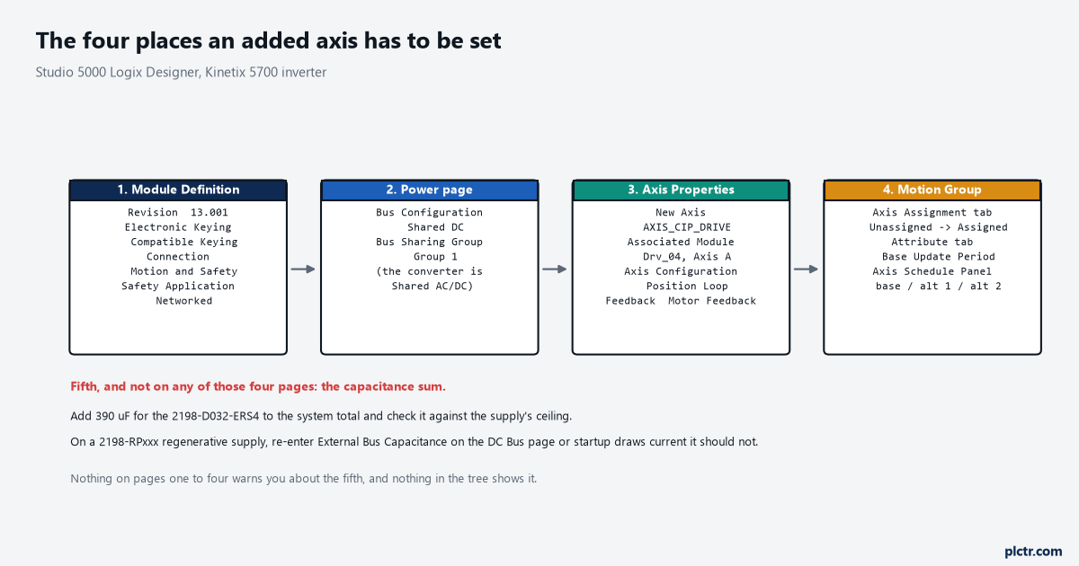
Left to right is the order to work in. The fifth item at the bottom is the one that has no dialog and no warning.
The axis, and the channel it is bound to
Right-click Motion Groups or the Ungrouped Axes folder, choose New Axis, and take AXIS_CIP_DRIVE.
The association is the part that decides which physical motor moves. On a single-axis 2198-Sxxx-ERSx there is one channel and no ambiguity; on a 2198-Dxxx-ERSx there are two, and the axis you create is tied to Axis A or Axis B of that module. Two tags, one module, one Ethernet connection carrying both. That pairing is why the second half of a dual-axis inverter is never quite as independent as it looks, and it is worth naming the axes so the relationship is visible: Infeed_04A and Infeed_04B beat Axis_7 and Axis_8 at three in the morning. Then the two dropdowns that set the control mode between them. Axis Configuration is Position Loop, Velocity Loop, Torque Loop or Frequency Control, and Feedback Configuration is Motor Feedback, Dual Feedback, No Feedback or Master Feedback; the pair of them, not either one alone, determines what the drive actually closes. A rotary servo on a ballscrew is Position Loop with Motor Feedback and that is the common case. Frequency Control with No Feedback exists on the Kinetix 5700 too, for an induction motor that does not need a loop closed around it.
The motor goes in next, and the quickest honest route is the catalogue number as the motor data source, which pulls the whole model in rather than leaving you typing nameplate data. Feedback assignment follows: the DSL connector for a Hiperface DSL encoder, the universal feedback connector for Sine/Cosine or EnDat, and one rule worth knowing before you plan a dual-feedback axis — the same port cannot serve as Motor Feedback, Load Feedback and Master Feedback at the same time.
Scaling, tuning and the hookup tests come after the axis exists. They are commissioning, not configuration, and doing them in the wrong order wastes an afternoon.
The motion group, and the axis that is not in it
There is exactly one motion group per Logix controller, and everything that moves has to be in it.
The instruction in the configuration manual is blunt: all axes must be added to the motion group in your project, and if you do not group them they remain ungrouped and unavailable for use. Open the group’s properties, go to the Axis Assignment tab, and move the new axis from Unassigned to Assigned. That is the whole operation, and it is the step that gets lost because the axis tag already exists, already shows the right module, and already looks finished in the organiser. Nothing faults. An MSO against an ungrouped axis simply does not do anything useful, and you go back to looking at the drive.
An ungrouped axis looks finished in the controller organiser and does nothing at all.
The Attribute tab on the same dialog is where the group’s Base Update Period lives, and adding an axis is exactly the moment to look at it. The Base Update Period is effectively the RPI of the unicast motion connection, and it also sets how often the Motion Task runs — a task that interrupts most other tasks regardless of priority. More axes in the group, more time per run. The rule of thumb printed next to the field is to keep the Last Scan time under 50% of the Base Update Period, and the general guidance is to keep the Motion Task under half the controller’s time on average. An Axis CIP Drive will go down to a 1 ms base; a PowerFlex 755T wants 2 ms, a 755 wants 3 ms and a 527 wants 4 ms. If the controller is already busy, measuring where the scan time is actually going before you add the ninth axis is a better use of an hour than arguing about it afterwards.
The fifth place, which is not a dialog at all
Nothing in Logix Designer adds up what the new module does to the bus.
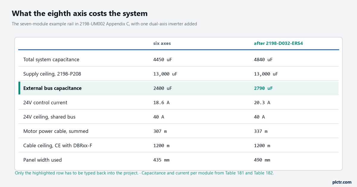
Four totals move and only one of them has to be typed back into the project. Everything else is a check you either do or skip.
A 2198-D032-ERSx is 390 µF. Add it to the sum of every power supply, inverter, capacitor module and accessory module on the same DC-bus group and compare the result against the supply’s supported maximum: 13,000 µF for a 2198-P208, 8000 µF for a 2198-P031 or 2198-P070, 26,000 µF for two 2198-P208 in parallel. The Appendix C example rail sits at 4840 µF against that 13,000, which is why it can take another inverter without an argument. It also adds 1.7 A to the 24V control-power total, against a 40 A ceiling on the shared 24V bus, and 4.0 A to the inrush the 24V supply has to survive. Its motor cable joins the group’s running total, which must stay under 1200 m for CE and UK compliance with 2198-DBRxx-F line filters.
Three of those totals are a check you either do or skip. The fourth is not.
On a 2198-RPxxx regenerative bus supply there is one number you must physically retype. External bus capacitance — the system total minus the supply’s own internal capacitance — is entered by hand on the supply’s DC Bus page, the manual says an accurate value is required for proper operation, and it does not update itself when you add a module. Leave it stale and the symptom is not a fault code but a behaviour: excessive current drawn from the AC input when DC-bus voltage regulation enables, and bus voltage that will not sit still. The panel work is the easy part by comparison — 55 mm of rail, a DC-bus link, the end cap moved along, and the drill-hole pitch from the rail layout rules.
The axis that connects but will not enable
The first thing everyone checks is the Ethernet address, and it is almost never the Ethernet address.
The drive’s own display tells you where the sequence stopped, and the CIP axis state on its home screen is more useful than anything in the controller at this stage. STANDBY means the drive is waiting to receive configuration from the controller, which points at the project rather than the network. CONNECTING means it is still trying to reach the controller at all. CONFIGURING and SYNCING are transient; SYNCING specifically is waiting for a successful Group Sync service, which is the motion group’s business. STOPPED means the DC bus is ready and the loops are not enabled, which is where a correctly configured axis waits for its MSO. PRECHARGE on the power supply means it is ready for mains. START INHIBITED means something is actively preventing enable and the drive knows what it is. Power the system up in the order the manual gives, because the order is not arbitrary: 24V control power first, watch the startup sequence, confirm the supply reaches PRECHARGE and the MOD and NET indicators behave, then apply three-phase. Control power before mains makes sure the shunt is enabled and keeps a nuisance Bus Overvoltage fault out of the commissioning log. After input power is applied the drive can take up to 1.8 seconds before it will accept motion commands, so an MSO fired from a first-scan rung will fail for reasons that have nothing to do with your configuration.
Once the axis reaches STOPPED and enables cleanly, the work moves to scaling and the first commanded move — what a MAM against a Kinetix 5700 axis actually needs is the next thing to have open, and the hookup tests before that. If this axis is going into a machine that is already running production, the sequencing argument is the same one as bringing a second rack of remote I/O online without faulting the first: decide what has to be off, and for how long, before you touch anything.