The servo-on command is made, the drive display sits at b01 or its axis number, RD never comes on and the machine will not start its home position return. No alarm, no warning, nothing flashing. A Mitsubishi servo home position that refuses to set is almost never the servo’s fault, and on an MR-J4-A configured as an absolute position detection system the behaviour has one overwhelmingly common cause, which is not the battery: unless ABSM is turned on, the base circuit cannot be turned on at all. The amplifier will hold the servo off, quietly, for as long as the PLC leaves pin 17 low. The battery does cause its own set of problems, the encoder causes another set, and this page separates them because the first hour of a machine that will not home is usually spent fixing the wrong one. If you are new to how an absolute encoder differs from an incremental one, the encoder types article covers the ground this assumes.
Every time SON goes on, the controller has to run an ABS transfer first. That is the deal.
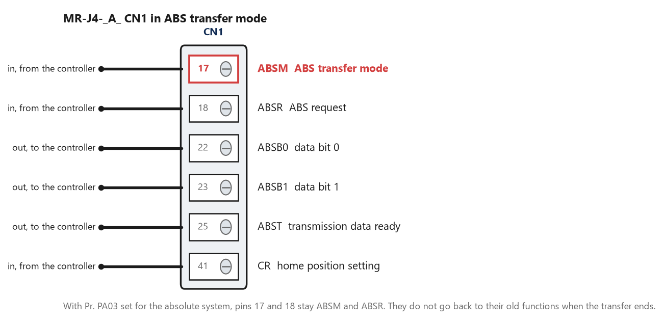
Six pins, and two of them are not doing what the wiring diagram in the drawer says. Once [Pr. PA03] selects the absolute system, pins 17 and 18 stay ABSM and ABSR whether a transfer is in progress or not.
What the amplifier is waiting for
[Pr. PA03] is the switch and it takes three values: 0 for an incremental system, 1 for the absolute position detection system over the discrete I/O, and 2 for the same thing over communication on amplifiers with software version A3 or later. Set it to 1 and six CN1 pins change meaning. Pin 17 becomes ABSM, the ABS transfer mode request; pin 18 becomes ABSR, the request for the next two bits; pins 22 and 23 become ABSB0 and ABSB1, the two data bits coming back; pin 25 becomes ABST, which the amplifier raises when the next pair is ready; and pin 41 is CR, the home position setting input. The manual puts a note under the table that is easy to skim past and expensive to miss, which is that pins 17 and 18 do not revert to their original functions when the transfer finishes. Whatever those two pins used to do in the incremental configuration, they no longer do it, and a machine converted from incremental to absolute by changing one parameter will have lost two inputs that the ladder still thinks it has. Change PA03 and check what used to be on those two pins before anything else. The transfer itself is a handshake and the controller drives it. The amplifier latches the current position when ABSM goes from off to on, sets that same value as its internal position command, and then feeds the 32-bit number back two bits at a time: raise ABST, wait for ABSR, drop ABST, wait for ABSR to drop, repeat. Sixteen of those cycles build the position, and three more carry a 6-bit sum check, so nineteen cycles in all before ABSM can go off and the base circuit can be enabled. On the controller side that is a shift-and-add loop with a watchdog, and the watchdog is not optional because both ends are timing each other.
Nineteen cycles, every power-up, before the amplifier will enable anything at all.
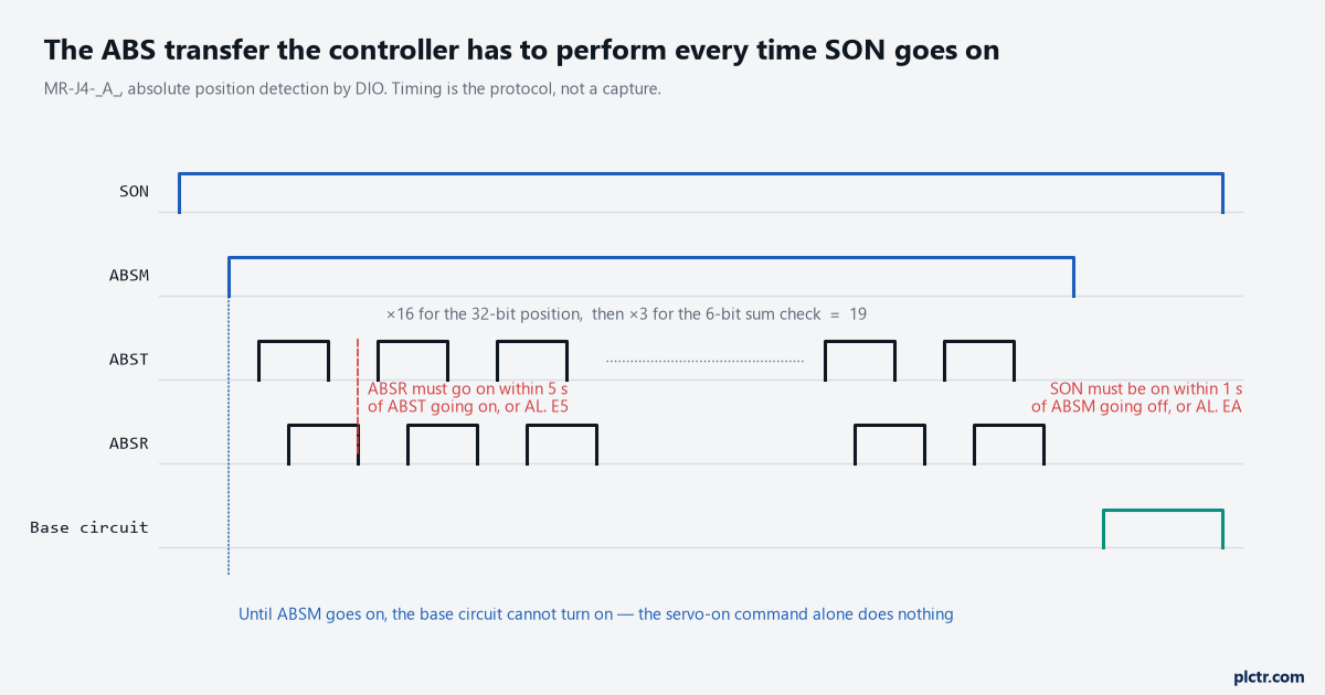
Nineteen ABST cycles, and four separate timers watching them. The one that catches most new programs is the last: SON has to be on within a second of ABSM going off.
The four clocks running during the transfer
The amplifier times the controller twice and the controller times the amplifier twice, and knowing which of the four fired tells you which end is at fault. If ABSR does not turn on within five seconds of ABST turning on, the amplifier calls it a transmission error and raises [AL. E5 ABS time-out warning]. If ABSR does not turn off within five seconds of ABST turning off, same warning. Going the other way, the controller is expected to treat ABST being off for a second or more as a transfer fault, and to treat the whole ABS transfer mode taking longer than five seconds as a transfer fault. There is a fifth, easy to forget: if SON is not on within one second of ABSM going off, the amplifier raises [AL. EA ABS servo-on warning]. E5 clears when ABSM goes from off to on again, which is why a machine can fail the transfer, retry, and look healthy while never actually enabling the base circuit. That is exactly why this failure is so quiet. The amplifier believes it is behaving correctly, the PLC believes it has issued a servo-on, and both are right. Put the transfer’s own signals on the HMI, or at minimum put ABST and ABSR in a fast trend for one power-up, and the question resolves in one cycle. A program that works on a two-axis machine and times out on a six-axis one is almost always a scan-time problem in that shift-and-add loop rather than anything wrong with the servo.
None of those five is a fault. They are warnings, and they do not latch the drive out.
The battery, and the thing everybody does to it
Here is the part that costs machines their home position, and it is entirely avoidable. [AL. 9F.1 Low battery] does not erase the absolute position data. The manual says so directly and then says how to replace the battery without losing anything: do it with the control circuit power on. Replacing it that way triggers AL. 9F.1 as a side effect of the momentary interruption and the data survives. Replacing it with the control circuit power off, which is what everybody does because it feels safer, is one of the two documented ways to erase the encoder’s absolute position on an MR-BAT6V1SET or an MR-BT6VCASE. The other is disconnecting the encoder cable. The MR-BAT6V1BJ junction battery exists precisely to get around both of those, because with it you can pull the encoder cable off the amplifier and change the battery with the power down.
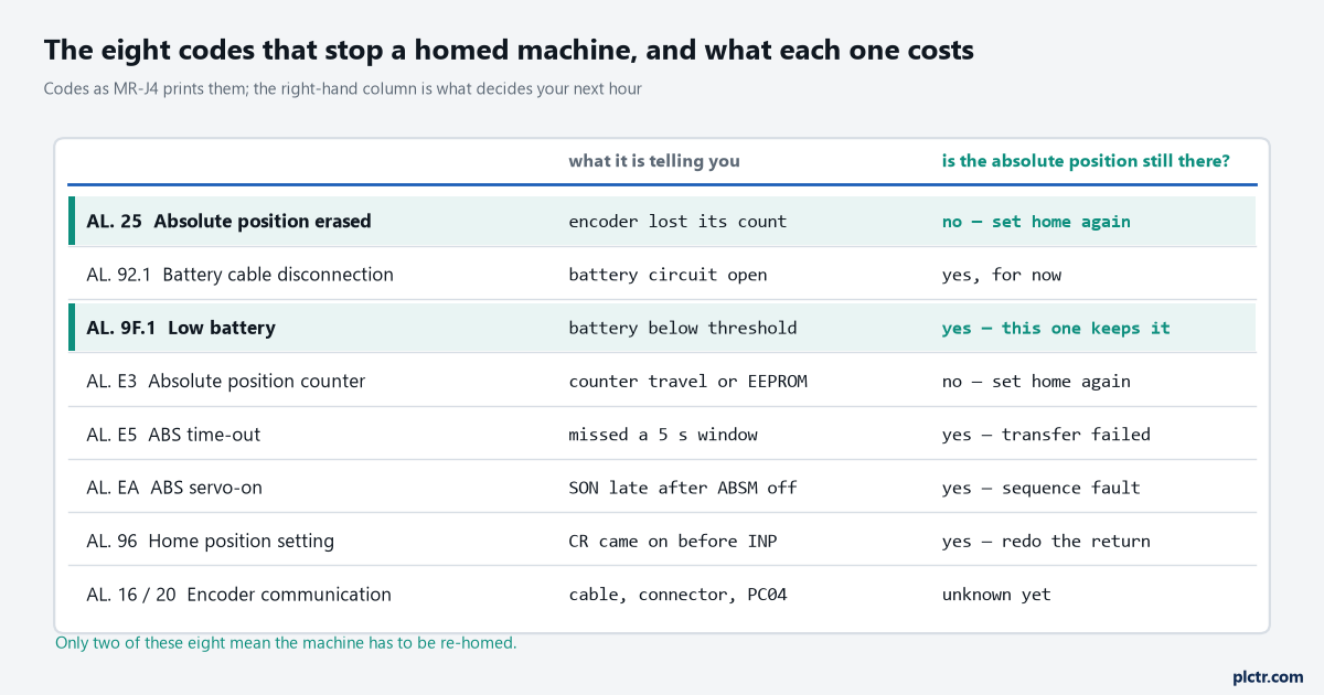
Only two of the eight actually cost you the home position. Working out which column you are in before touching the machine saves the re-homing that was never necessary.
Replace it live. That one sentence is worth more than the rest of this section.
The numbers worth knowing: battery life is five years from the production date regardless of whether it is connected, and the manual asks for replacement within three years of the machine going into service. A battery bought two years ago and left in a drawer is not a fresh battery, and fitting one is how a planned maintenance job turns into a call to re-home eight axes. A related trap sits at the other end of the machine’s life. [AL. 25 Absolute position erased] at the very first power-on after the encoder cable was connected is normal and expected, and the manual’s own startup procedure says to clear it by cycling the power once. That is not a fault, it is the encoder announcing it has never been homed. A rotary servo motor in an absolute system will do it every time on a new install and the only thing you need to do afterwards is set the home position.
What erases a Mitsubishi servo home position without going near the battery
Five parameters will throw the home position away at the next power-on, and none of them looks dangerous while you are typing it. Change [Pr. PA06] or [Pr. PA07], the electronic gear numerator and denominator, and the home is gone. Change [Pr. PA14], rotation direction selection, and it is gone. Change [Pr. PT08], the home position return position data, or [Pr. PT28], the number of stations per rotation, and it is gone. The scenario that puts this in an article rather than a footnote is familiar: somebody finds the axis is out by a consistent ratio, corrects the electronic gear to fix it, downloads, cycles power, and now the machine will not home and there is no alarm to explain why. The gear change was correct. The home position went with it because the coordinate system it was expressed in changed underneath it. Restrictions are worth a pass too, because some machines cannot have an absolute system at all.
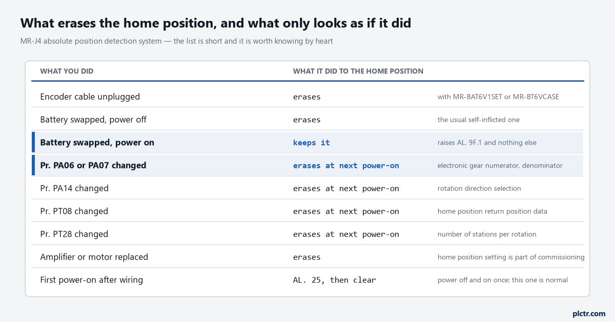
Nine ways in, and the two highlighted rows are the ones worth remembering. The second one is the good news.
The manual rules it out in speed and torque control modes, in the control switch-over modes, on a stroke-less coordinate system such as a rotary axis or an infinitely long positioning axis, when the electronic gear is to be changed after home position setting, when alarm code output is used, and with the incremental value command method. A rotary indexer that somebody wants to keep absolute is the common casualty. The range is finite too: the home position plus or minus 32767 revolutions on a rotary servo motor, which sounds enormous until a ball screw with a fine pitch runs a long axis.
One number to respect during a power cut: 6000 r/min.
That is the maximum shaft speed the encoder can track on battery backup on a rotary servo motor, and the manual qualifies it, only when acceleration to 6000 r/min takes 0.2 s or more. There is a separate caution that switching power on while the motor is turning at 3000 r/min or more can cause a position mismatch from external force. A vertical axis that free-falls when the brake drops, or a spindle still coasting when somebody reinstates the supply, is how an absolute machine loses a position that no battery fault ever touched.
When it really is the encoder
Encoder faults announce themselves, which is the one mercy in this subject. [AL. 16 Encoder initial communication error 1] fires at power-up before anything else gets a chance to happen, [AL. 1E] and [AL. 1F] are its siblings for the later stages of that same initial handshake, and [AL. 20] and [AL. 21] are the normal communication errors that turn up once the axis has been running. Before anybody starts cutting cable ties, check one parameter. Four of the long encoder cables, MR-EKCBL30M-L, MR-EKCBL30M-H, MR-EKCBL40M-H and MR-EKCBL50M-H, are four-wire types, and [Pr. PC04] has to be set to 1 _ _ _ to tell the amplifier which it is looking at. Get that wrong and the amplifier raises AL. 16 at every power-up with a cable that is electrically perfect, which on a machine re-cabled last weekend with a longer run sends people up a ladder for no reason at all.
A perfect cable and the wrong PC04 look identical from the front of the panel.
Where to start tomorrow morning
Read the display first, and read it for warnings rather than alarms; warnings are three characters like 9F or E5 and they do not latch the drive out. If there is nothing there, put ABSM, ABST, ABSR and RD in a trend and power the machine up once. If ABSM never goes high, the problem is in the PLC’s power-up sequence and no amount of work on the servo will find it. If ABSM goes high and the nineteen cycles stall, count how far it got before it stopped, because a transfer that dies at the same cycle every time is a logic bug and one that dies at a different cycle is a timing one.
Then, and only then, worry about the battery. It is rarely the answer and it is always the first suggestion. A structured fault-finding order is worth more here than product knowledge, because the machine is not broken, it is waiting. If the comparison helps, this whole handshake is the work that a Logix motion axis hides inside its own instructions, where the axis either has an absolute feedback device configured or it does not and the ladder never sees the transfer at all.
If the home position genuinely is gone, set it with the actuator stationary and INP on, hold CR for at least 20 ms, and write the date in the machine log. The amplifier will accept a data-set home 100,000 times and a dog-type home a million, so the count is not the constraint; knowing when the last one happened is what you will want in six months.