Write a torque reference into DINT 1 of a PowerFlex 755’s output image and the drive will run at that many hertz. DINT 1 is the Reference, it is a 32-bit REAL, and 750COM-UM001 says plainly what it scales to: drive speed, in whatever P300 [Speed Units] is set to. There is no torque word in the base I/O image at all. PowerFlex torque control from a ControlLogix means putting the number into a datalink that points at a torque parameter, and then making three other parameters agree that the drive is a torque regulator today.
The datalink is the easy half. The agreement is where the afternoon goes.
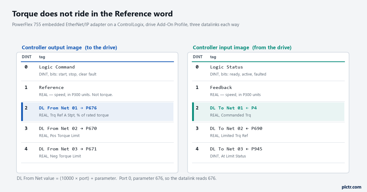
The Reference word is speed and stays speed. The torque setpoint rides in the first datalink, pointed at P676 by the formula in the middle of the manual: ten thousand times the port number, plus the parameter.
The parameter that has to be right before any of the others matter
P35 [Motor Ctrl Mode]. If it is 1, Induction SV, which is the factory default on a 755, then every parameter below is inert and the drive will smile at you while ignoring all of it. 750-PM001 repeats the sentence under each torque parameter in turn, which is unusual for a Rockwell manual and tells you how often the question gets asked: only active in Flux Vector motor control modes. The options that qualify are 3 Induction FV, 6 PM FV and 10 IPM FV. Getting there is not just typing a 3, either. Flux vector control is built on a model of the motor, and that model comes either from P70 [Autotune] set to 1, Calculate, which works the numbers out from nameplate data, or from a Static Tune or a Rotate Tune that measures them. A rotate tune spins the motor uncoupled and is the only one that measures the flux current properly; a static tune is what you run when the load cannot be disconnected. If P70 still reads 1 and somebody is asking why the torque is 15 % out, that is the answer.
The mode parameter comes next and it is the one that gets typed into the wrong place. P309 [SpdTrqPsn Mode A] is the first of four, P309 through P312, holding modes A, B, C and D. Set the one you want to 2, Torq Reg, and leave the others alone unless you are switching between regulators with a pair of digital inputs, which is what P181 and P182 [DI SpTqPs Sel 0/1] are for: both low selects A, and the other three combinations select B, C and D. What you must not do is map a datalink onto P309 and write it every scan from the PLC. It is a configuration parameter, the drive is entitled to treat it as one, and the selection mechanism Rockwell built for run-time switching is the digital-input pair. If the modes need to change from the controller, put the two selects on bits the PLC owns and switch those.
Two parameters, one mode, and no cyclic writes to anything the drive stores.
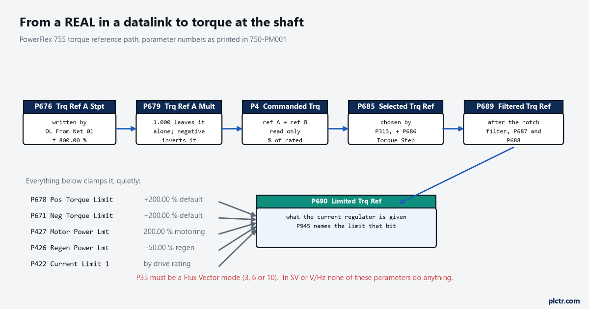
Five parameters deep, and every one of them is readable. When the shaft is not doing what the PLC asked, the mismatch is visible somewhere along this row.
What the number turns into on the way to the shaft
The chain is longer than most people expect and each link is a readable parameter, which is the reason this is a solvable problem rather than a mystery. P675 [Trq Ref A Sel] chooses where reference A comes from, and it defaults to 676, meaning the digital setpoint P676 [Trq Ref A Stpt] that the datalink writes; there is a second, parallel reference B with P680 and P681, and the two are summed. P679 [Trq Ref A Mult] multiplies reference A afterwards, defaults to 1.000, and inverts the reference if you give it a negative number, which is a neat way to flip a winder from pay-off to take-up without touching the PLC. The sum lands in P4 [Commanded Trq] as a percentage of rated motor torque. P685 [Selected Trq Ref] shows what the active mode actually selected, gets P686 [Torque Step] added to it, and passes into the notch filter set by P687 and P688, whose output is P689 [Filtered Trq Ref]. Then the limits get their turn and what survives is P690 [Limited Trq Ref], which is the number the current regulator is really given. Which limit is clamping is not a guess: P945 [At Limit Status] is a 32-bit word with a bit for each, and it names the torque limits, the motoring and regenerating power limits, the current limit, the bus voltage limit and a dozen others. The defaults are the trap. P670 [Pos Torque Limit] ships at 200.00 % and P671 [Neg Torque Limit] at -200.00 %, P427 [Motor Power Lmt] at 200.00 %, and P426 [Regen Power Lmt] at -50.00 %. That last one catches people on hoists and winders, because a machine that is happy motoring at 120 % finds itself clamped at half that as soon as the load starts driving the motor.
P4 and P690 belong on the same screen. Different values mean something is clamping.
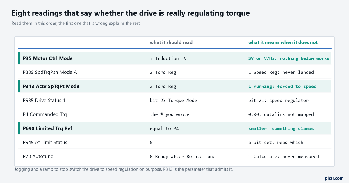
Read down the list and stop at the first row that is wrong. The rows below it will be wrong as a consequence and fixing them individually wastes the morning.
The check that catches the drive lying to you politely
P313 [Actv SpTqPs Mode] is read-only and it is the most honest parameter on the drive. It shows which regulator is actually running, as distinct from which one you asked for in P309, and 750-PM001 is explicit that the drive will sometimes override the selection. Jogging does it. A ramp to stop does it. SLAT Min and SLAT Max, the two speed-limited adjustable torque modes used on web handling, do it constantly by design, sliding between torque and speed regulation depending on how the speed error compares with the torque reference. So a drive that behaves like a torque regulator for most of a cycle and then suddenly holds speed is not faulty and is not misconfigured; it has told you, in P313 and in P935 [Drive Status 1] bits 21 to 23, exactly what it did and when. Map P313 into a datalink and log it alongside P4, and the “it sometimes goes weird on the stop” conversation ends in about ten minutes.
The other check is the one nobody enjoys writing down, because it is about what happens when the load goes away.
A torque regulator has no speed loop. Ask for 60 % torque with a broken web or an empty hook and the motor accelerates until something else stops it, and the only something else is P520 [Max Fwd Speed] and P521 [Max Rev Speed]. Those are not comfort settings in torque mode, they are the machine’s protection, and they want to be set to a speed the mechanics can survive rather than to the motor’s nameplate. P524 [Overspeed Limit] sits above them and fault 25, OverSpeed Limit, needs the condition to last 16 ms before it trips, which on a light load is a long time. Setting those two properly is the difference between a torn web and a wrecked gearbox.
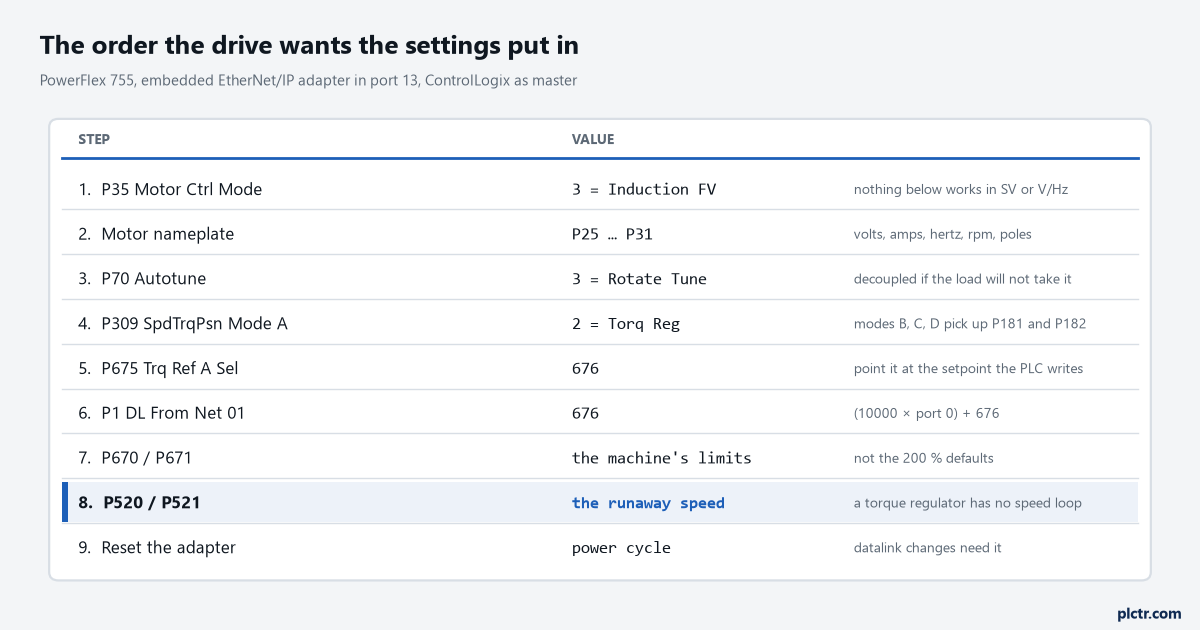
Step 9 is the one that makes people think the drive is broken. Datalink changes do not take effect until the adapter is reset or the drive is power cycled.
Getting the datalink right the first time
Datalinks are numbered parameters on the adapter, not on the drive, and they are pointers. Parameters 1 through 16 are DL From Net 01 to 16 and carry controller-to-drive data; 17 through 32 are DL To Net 01 to 16 and come back the other way. The value you put in each is an address, built as ten thousand times the port number plus the parameter number, so the drive’s own P676 is simply 676 because the drive is port 0, while parameter 3 of an encoder card in port 5 would be 50003. Two rules from 750COM-UM001 save real time here: use them in consecutive order starting at the first one, because a gap makes the network connection larger than it needs to be, and reset the adapter or cycle drive power after changing them, because they are read at connection time.
Consecutive from the first one, and a reset afterwards. Both rules cost nothing to obey.
Adding the drive with its Add-On Profile is worth doing rather than using the Generic Profile, since the profile names the tags and formats the REALs; with the Generic Profile the image is integer-based and every REAL needs a COP or a user-defined type to get across.
Three out and three back is enough to start: the setpoint and the two torque limits going down, P4, P690 and P945 coming home. If the drive is on the same segment as the rest of the cell, the connection behaves like any other EtherNet/IP I/O connection and the RPI matters for how fast the torque reference can change. Where the application really is coordinated motion rather than a torque setpoint, the answer is a different one entirely, and Logix motion instructions with a Kinetix drive is the road to look down before going further with datalinks. For a plain single motor driven from ladder, the command word and speed reference route is simpler and you should not be here at all.
Before the first run, put P4, P690, P945 and P313 on one screen and turn the machine empty at 10 % torque. P690 tracking P4 with P945 at zero means the chain is right.