The display reads TORQUE TRIP CLOSED, the IQ40 on the raw water isolation valve has stopped short of its closed limit, and the operator has pressed close four more times with nothing happening. That second part is not a fault: PUB002-040 says that once the actuator meets its set torque between the limits it stops and has to be reversed before it will move that way again, so pressing close does nothing at all until somebody drives it open first. What there is instead of a torque switch is a pair of numbers, 3/16 Close Torque and 7/16 Open Torque, each settable between 40 % and 100 % of the actuator’s nameplate rated torque, and a second pair of settings that can switch the protection off over part of the stroke entirely. Everything below comes out of the two publications that ship with the actuator: PUB002-040, the full configuration, status and monitoring manual, and PUB002-039, the instructions for safe use, installation, basic setup and maintenance. The trip you are looking at is one of those three things: a valve that genuinely needs more torque, a limit set too low for it, or a breakout band that let the torque climb unchecked until the band ran out.
There is no torque switch to adjust. There has not been one for a long time.
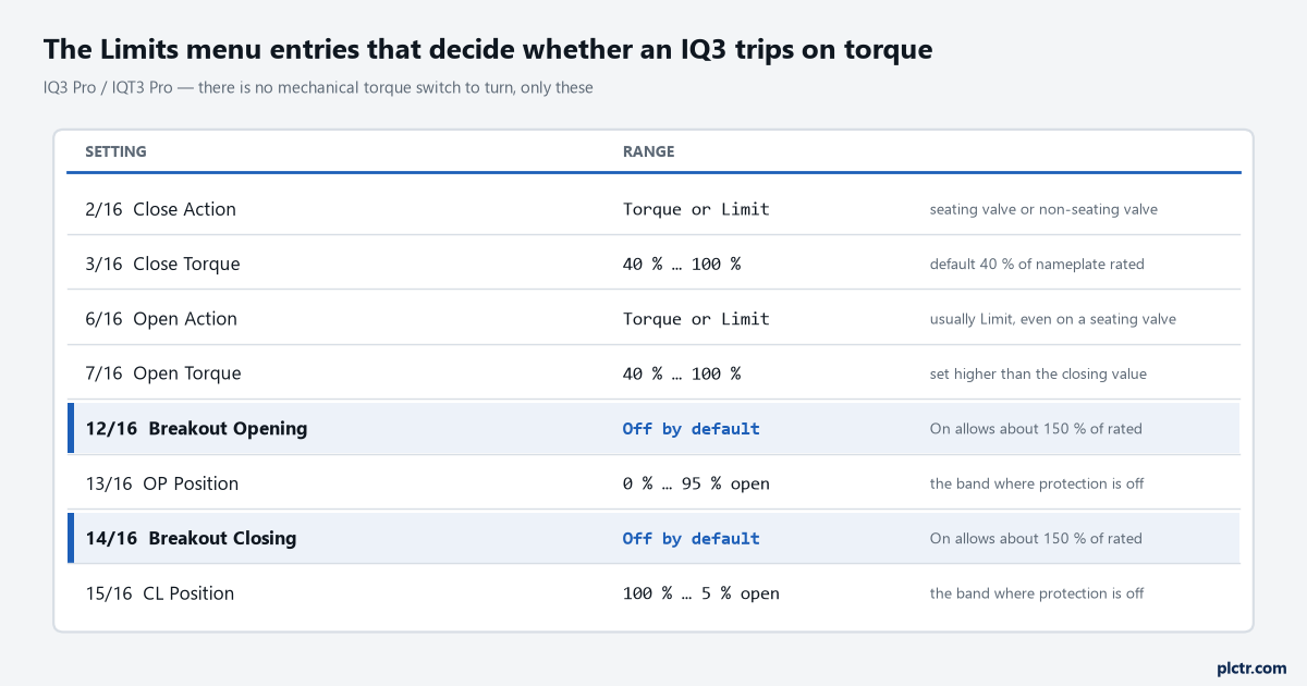
Eight menu entries and no hardware. The two highlighted rows are the ones that change what the other six mean.
Torque or Limit, and why the answer is usually Limit
Before anything else, check 2/16 Close Action and 6/16 Open Action, because an actuator set to close on torque on a valve that should close on limit will trip on torque every single cycle and there is nothing wrong with it. Rotork prints a valve type table for exactly this, hedged carefully with the note that it applies only in the absence of an instruction from the valve maker, who gets the last word. Wedge gate and globe valves close on torque and open on limit, because they seat and the seating needs load. Butterfly, through conduit, ball, plug, sluice gate, penstock and parallel slide are all limit in both directions. So a ball valve reporting TORQUE TRIP CLOSED at its closed position is not worn and is not stiff; it is configured to seat a valve that does not seat, and the fix is a menu entry rather than a work order. The same reasoning runs backwards: on a wedge gate that closes on torque, a trip at the closed position is the actuator doing its job, and the thing to look at is whether the seating torque has crept up over months rather than whether it tripped at all.
An actuator seating a gate valve is supposed to trip. That is what seating means.
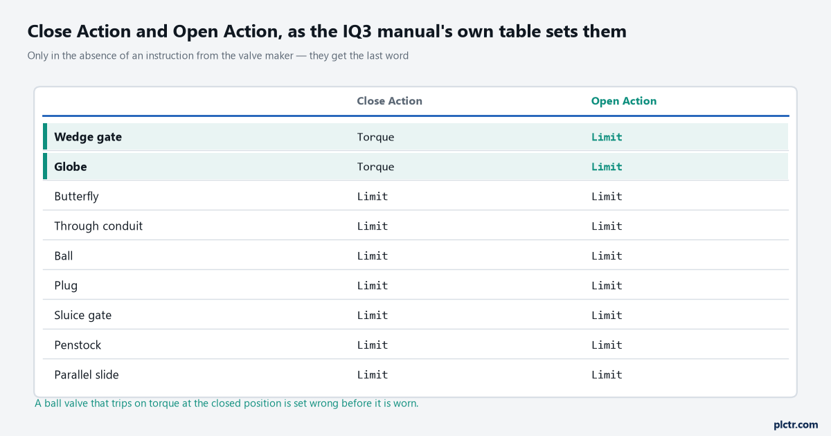
Rotork’s own default table, and worth checking against the valve tag before anybody decides the valve is at fault. The valve maker’s instruction overrides all of it.
The setting that hides the problem for most of the stroke
Breakout torque is the feature that turns a straightforward diagnosis into a puzzle, and it is off by default for good reason. Turn 12/16 Opening or 14/16 Closing on and the actuator will deliver approximately 150 % of rated torque over a band of the stroke that you choose in 13/16 OP Position or 15/16 CL Position, with the torque limit protection simply not applied inside that band. The opening band runs from the closed limit up to any point between 0 % and 95 % open; the closing band runs from the open limit down to any point between 100 % and 5 % open. Outside the band, protection reverts to whatever is set in 7/16 or 3/16. The feature exists for a real reason, which is unseating a sticky valve that has sat in one position for a year, and Rotork is blunt about the price: the valve maker or the integrator has to confirm that the valve structure and the interface components can survive the extra torque and thrust before anybody switches it on. Now think about what that does to a fault. A stem that starts to bind at 55 % open on an actuator whose opening breakout band was set to 70 % will be pushed through that binding at up to 150 % of rated, silently, and will trip the instant it crosses 70 % because the protection comes back at that point. The trip is recorded at 70 % open. The problem is at 55 %. Anyone who goes to the valve, opens the bonnet at the position the log reports and finds nothing wrong has been sent there by a setting rather than by a fault, and the second and third visits usually go the same way.
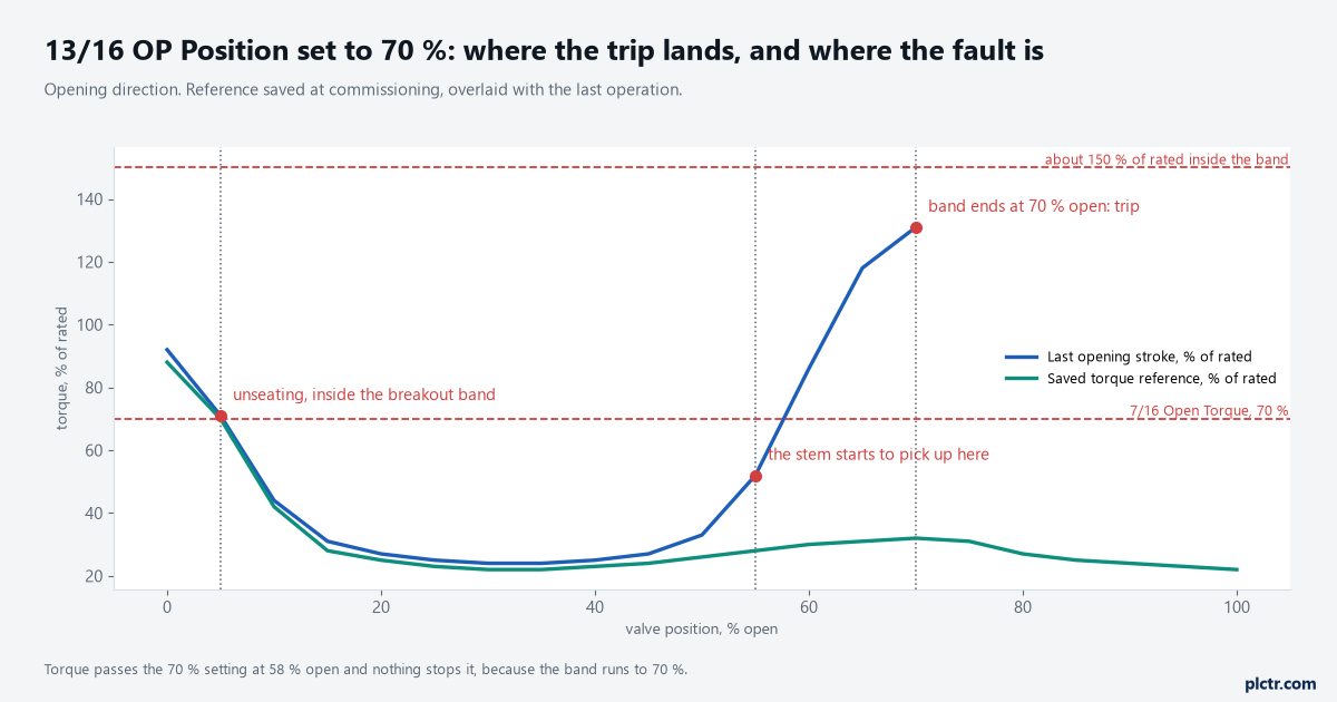
Worked from the settings described, not captured. Torque passes the 70 % limit at 58 % open and carries on; the trip records the edge of the band, which is the one position on the stroke where nothing is wrong.
That is the single most useful thing on this page. A mid-travel trip at a suspiciously round position is a band edge until proven otherwise.
The second hider: service alarms that ignore seating
The Hi and Hi Hi torque alarms look like the answer to all of this and they are only half of it. Rotork’s own example in the manual sets a trip level at 80 %, a Hi alarm at 70 % and a Hi Hi at 75 %, so the alarms warn before the trip rather than after. What the manual then says is the part that matters: Hi and Hi Hi deliberately ignore valve seating torque trips and are only generated when mid-travel torque exceeds the set levels. That is the right design, because a gate valve that seats at 85 % every cycle would otherwise alarm every cycle and everybody would switch it off within a week. It also means those two alarms are blind to precisely the seating that is drifting upward, and if the machine you are chasing is a wedge gate whose seating torque has gone from 62 % to 88 % over two years, no service alarm will have told anybody. They are indication only in any case; they do not stop the actuator the way a torque trip does. The same screen carries the rest of the service alarm levels and they are worth setting while you are in there, because the manual’s own examples show the scale intended: a Max Starts per Hour alarm at 50 starts against a displayed value of 1200, a Total Starts alarm at 5,000, a Total Turns alarm at 15,000, a vibration level anywhere between 1,000 mG and 8,000 mG, and a service interval in months. None of those stops anything either. All of them are the difference between finding out in a planning meeting and finding out at three in the morning.
Two counters do record it, and they are in the service log.
What the actuator already knows
Nobody needs to guess at any of this, because an IQ3 keeps a log and most sites never read it. The service log carries, for the closing direction, the maximum applied close torque as a percentage of rated and the date it happened, the time and date of the last torque trip, and separate counts of how many times the Hi and Hi Hi alarms have been triggered; then it carries the same five fields again for the opening direction. That is enough to answer the only question worth asking first, which is whether this trip is new. A maximum of 96 % recorded eight months ago against a Hi count of 340 says one thing; a maximum of 96 % recorded last Tuesday against a count of 2 says something entirely different, and only one of them is a valve problem.
Read the counts before the numbers. They say whether anything has actually changed.
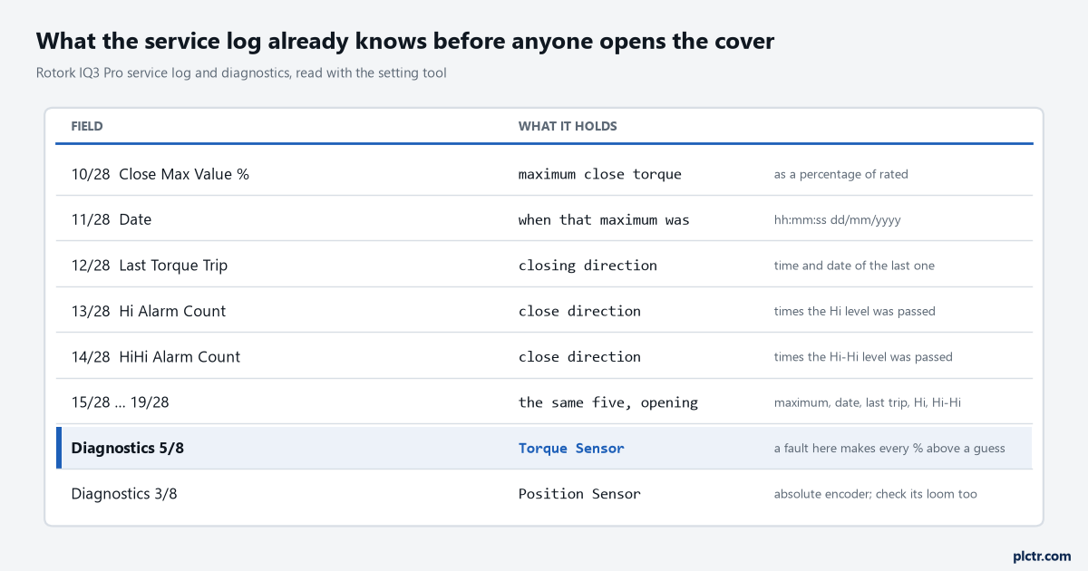
Ten log fields, five per direction, and two diagnostics. The torque sensor diagnostic comes first, because a fault there makes every percentage above it a guess.
The data log goes further and it is the reason to save a torque reference at commissioning. Valve Torque Live draws torque against position for the current stroke and overwrites itself each time; Valve Torque Profile shows the average from the start of the log with the last operation drawn over it; Valve Torque Reference shows a profile you saved deliberately, with full operating conditions present, after the actuator and valve were commissioned. The last of those is the one that answers “has this changed”, and saving it takes about two minutes at handover. On an actuator where nobody saved a reference, the averaged profile is the next best thing, because a tight spot that has developed since the log started will still stand out against the average even though the average has been quietly absorbing it.
Save the reference at commissioning. In five years it will be the only honest baseline anyone has.
Some of that data leaves the actuator on its own, and the detail matters if you are reading it upstream. With the Pakscan option fitted and its torque log filter set to Auto, the actuator reports six historical torque logs for each direction as soon as it has stopped at a limit, and those logs carry the instantaneous torque values. Set the same filter to Manual and nothing is pushed; the master station asks for the logs when it wants them, and what comes back is the averaged data rather than the instantaneous. That is a real difference when you are hunting a tight spot, because averaging is exactly the operation that makes a tight spot disappear. Profibus, Modbus, HART and Foundation Fieldbus are the alternatives on the same range, each with its own entry in the remote control menu, and whichever is fitted the torque number is worth more upstream than the open and closed contacts everybody settles for.
Before you blame the valve, check the sensor
The IQ3 diagnostics screen has eight entries and two of them decide whether anything above can be trusted. Entry 5/8 is the Torque Sensor, and when it is active the manual’s instruction is to check the torque sensor and its loom. A failed or intermittent torque sensor makes every torque percentage on the display, in the log and on the network a work of fiction, and it can produce trips that look exactly like a stiff valve. Entry 3/8 is the Position Sensor, the absolute encoder, and a fault there corrupts the position half of every torque-against-position graph in the previous section, which is worse in a way because the numbers still look plausible. The other six entries are worth a glance on the same visit: Mains Fail, Phase Loss, Hardware Option, Network Alarm, Config Error and MEM Missing, the last of which means the EEPROM holding every setting and calibration is not there. Two alarms sit next to the trip and get confused with it. Valve Obstructed is raised when the valve is obstructed or the set torque limit has been reached, which makes it a companion to the trip rather than a separate event. Motor Stall has a precise definition worth memorising: a valid command received and no movement detected within five seconds. Those are different failures. A stalled motor with no torque rise is an electrical or mechanical drive-train problem; a torque trip with no stall is a load problem or a setting. Where it matters for the control system is in what gets wired back: the relay contacts can be configured as Torque Trip CL, Torque Trip OP, Torque Trip for either direction, or Torque Trip Mid for mid-travel only, and Valve Alarm combines a mid-travel torque trip with a motor stall into one signal. If the DCS only ever sees Valve Alarm, it cannot tell those two apart, and neither can the person it calls.
Give the mid-travel trip its own contact. It is the one that means something changed.
The mechanical interface deserves one look before the valve takes the blame, and PUB002-039 supplies the numbers for it. Its side-mounting instruction is to check that the mounting flange is at right angles to the input shaft and that the drive bush fits the shaft and key with adequate axial engagement, which is worth confirming on any actuator whose torque profile has moved since it was installed. The flange fixing torques sit in the same section, and they are not small: an F25 base on M16 bolts at 219.8 Nm, an F30 on M20 at 430.5 Nm, an F10 on M10 at 51.6 Nm, with the separate securing bolts at 45.9 Nm for M12 and 101 Nm for M16. An actuator working against a mounting that has loosened is producing torque that never reaches the stem.
On a non-integral installation the logic sits outside the actuator entirely. IQ SET actuators bring their torque and position limit contacts out to the MCC, wired into the open and close contactor coil circuits so that reaching a limit opens the contact and drops the contactor, with those circuits held to 150 V maximum. That arrangement gives a PLC no torque number at all, only the fact that something stopped, which is a good reason to take the network option on anything you expect to diagnose remotely. Where an actuator is part of a wider water or wastewater control scheme, the torque trend is the single most useful thing it can send upstream, and it fits naturally into the same condition monitoring story as motor current and vibration.
Next time one trips, read the service log before you touch the setting tool, and write down the direction, the position and whether breakout is on for that direction. Those three facts decide whether the next hour goes on the valve or on the configuration, and a disciplined order of checks is worth more here than familiarity with any one actuator.